Leaderboard


Popular Content
Showing content with the highest reputation on 01/17/16 in all areas
-
Since the unveiling of our A series amplifiers and before, I get the occasional email that reads "hey, I know you're busy, but could you design a few amps for me real quick" It usually makes me giggle a little and then smh. It takes me back to 1999 right before I started with RF. I also had no idea what was involved designing an amplifier from the ground up. No disrespect intended if you are reading this and have asked me to make you some amps before. How would you know what is involved if you haven't done it before? This has prompted me to go through literally thousands of photos on my phone and pull off any amplifier design pictures that have to do with the new amplifiers we just introduced. I will make my best attempt at posting them here in chronological order, and make some brief comments here and there. I also threw in a few pictures of my daughter taken during those times as a measure of time. The A series amplifiers are a direct COPY of the home audio amplifier I designed for my own use (changed power supply to 12VDC, added fans, remote turn on, balanced/unbalanced input and ability to put it into Class A/B mode (home amp is always class A)) so I have included the photos of designing that as well because all of the time I spent developing the circuits went directly into the mobile amplifiers. Ok enough of me talking.. On with the show! Before I build any circuit I like to try to simulate it in PSPICE, here you see a nice clean output and the predicted distortion My daughter was born during this time Here you see the power supply for the home amp. AC to DC supplies like this are very easy to design. The small circuit board is the input stage and voltage amplifier stage. This is where a lot of the magic is and many months of reading and testing were done to get it to work. Unfortunately I couldn't find any pictures during that time. We went through at least 3 different voltage amplifier designs, PCBs and testing before we came up with what we use today. Moved tested input stage and voltage amplifier stage onto main PCB instead of it having it's own PCB. (In the car amp it still has its own PCB for the least amount of noise possible) Each tiny resistor and transistor has been studied for voltage, current, and power dissipation. Prototyping the current amplifier stage It works! Now lets build 2 voltage amplifiers, 2 current amplifiers, connect them together and add a power supply! We also added a prototype SMD VU-DIN meter for S&G. Ok let's put this contraption in some kind of case so we can move it around without breaking anything. A SMD AD-1 Amp Dyno prototype case worked well Keeping the same case, I designed a simple face plate for it and had my machine shop CNC it. We put it all together with some prototype meters. Shown here on the distortion analyzer making a sweet ass sine wave with only 0.0068% THD! WHOA! Cleanest amp i've ever tested, home, pro, or car.10 points
-
Now that we know the electricals are mostly sorted, lets check this heatsink design and see if we have enough dissipation capability. A fairly common industry test is full power sine wave into 2 ohms, and 40% power sine wave into 2 ohms. The first case stressing the power supply, the second case stressing the output section. Time to put that foam core board lid back on. I don't have photos to show, but we blew it up several times. The problem was we couldn't get the heat from the power devices (power supply MOSFETs and output section BJTs) into the heatsink fast enough. Between the power devices and the heatsink you need an electrical isolator because the mounting surface of the MOSFET or BJT is connected to the center leg of the device, which has various voltages on it that you wouldn't want on the heatsink. This would cause the amplifier to not work at all. The most basic of amplifier designs use kapton tape, it is a great electrical isolator, but a terrible conductor of heat. We didn't even try kapton because I wanted this thing to perform! The next level is various thin composite materials. One of these materials turned out to be good enough for the home amplifier and if you look at some of those pics you will see a thin grey pad under the devices. We wanted better than that because at low impedance we want to be reliable. If this topic interests you check out http://www.fujipoly.com/usa/ After weeks of testing different materials we settled on some stuff from this place that is tan in color and has a high thermal conductivity. http://www.aavid.com/products You can see it in the next series of photos.5 points
-
The machine shop usually takes about a month after I give them my CAD files so I better get to designing the heatsinks and baseplate because I'm not going to be able to test the amp with foam heatsinks! Two months and revisions later we have some aluminum! 17 pounds of it for 1 amplifier! Ok back to the power supply and current amplifier PCB design. As it turned out, I needed to use a 4 layer PCB. Like 4 circuit boards in 1, literally in layers sandwiched together. Typical PCBs in electronics have a copper thickness called 1/2 ounce. This means that for a square foot of PCB there is 1/2 ounce of copper in it to carry the current. In our design we are going to need a LOT more than that. 4x that actually so we went with 2 ounce copper, 4 layers of it. Each color you see here is copper on a different layer of the PCB. Many, many late nights later I am ready to send the files off to the PCB house and order all the components to build one. Now that this PCB is done, I get to do it all over again for the right hand PCB. No there is no magic button I can press to tell my software to do the opposite of the whole board for the other side. If you try that it will reverse all of the "footprints" for the components and when you build it every part will be in backwards and some of them can't go on the board any other way. Ask me how I know this.... $600 down the drain. Eventually I had to make the right hand board from scratch like the left hand one.4 points
-
Let's test it. Wait what? Only 0.0095% THD at 20kHz! That is nuts! I bet it's amazing at 1kHz! (Distortion always goes up with frequency, always) Here it is at 1kHz I was just as skeptical but didn't have any better test equipment at this time. So we trusted it as the truth and moved on. Let's play some music already!4 points
-
I send my PCB design files off to the PCB house along with some $ and in a week I have some PCBs! During this waiting time we ordered up all the components for the PCB so they arrive about the same time. I choose the best capacitors I could find for the audio paths, Nichicon FG (fine gold) and Nichicon Muse (green). My partner Juan is magical with a soldering iron and debugging so it's his turn now. Let's drill these new 'sinks for the PCB mounting holes and transistor mounting holes Proud papa Magic Juan Testing the supply, only 180V DC4 points
-
Time to give props where they are due. I've learned a lot about amplifier design over the years from some of the best. Besides the books shown here I also worked with Jim Strickland and Mark Albers daily for years . The next step here is to design some heatsinks, make them, dump heat into them and see how they react. I don't have pics from that time but this is the result, the tunnels increase the surface area of the heatsinks big time! Surface area is what you need to move the heat to the atmosphere. The holes are 0.750" diameter. So the surface area lost by having the holes is (.750 / 2) ^2 * pi x 2 (top and bottom) = about 0.88 square inches x 39 holes = 34 square inches. BUT the amount of surface area gained is (.750 * pi * 7 inches deep = 16.5 square inches x 39 holes = 643 square inches! So each hole effectively gave us 20x the surface area. Not to mention a great chimney effect that starts to flow air without a fan. Lets make a set of mechanical and have them anodized black Now we need to loose all the prototype stuff and design the actual PCB that will contain the voltage stage, current stage and sit nicely on our new heatsinks4 points
-
About 1/2 of the small class D full range amps on the market today are just a chip amp with a power supply. A chip amp that rolls back like crazy when it gets hot. A chip amp who's design makes it very difficult to heatsink properly. Sound like a recipe for never making rated? Yep. http://www.digikey.com/product-detail/en/TAS5630DKDR/296-24624-1-ND/20917223 points
-
Some people want to be like Messi or Ronaldo when they grow up. I'm an EE Student and want to be like Tony D'Amore.3 points
-
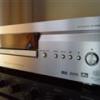
Time to make sure everything fits and to paint the top covers We literally sprayed these the night before leaving to CES in a cold shop! Into a heated room for the night it goes Time for some testing Lid on, lets fire her up3 points
-
So it looks like the heatsink design is more than enough (even though we are not satisfied with the temperature delta between the power devices and the heatsinks yet). So at this point we called in a good friend who is a mechanical engineer to design the sheet metal top, front cover, top meter cover, and associated parts. I gave him the drawings that I had and in no time at all he sent this rendering and asked "like this?" He is the man, thanks Tom Sollars. We loved it and asked him to continue and order up some of these parts when done. A few weeks later we had these3 points
-
Now that we know we have a stable amplifier design, we could change the power supply from the AC/DC supply to a DC/DC supply that can run from 12V and convert to 100-120VDC. The home amp runs at 180VDC, but it is designed to run at 8, 4 and 2 ohms. I want the mobile amp to run at 4, 2 and 1 ohm so we need less voltage to make the same power. We also need a mechanical concept. All we knew at this time is that we wanted it to be a TRUE dual mono. This means 2 amplifiers, each with their own power supplies. I'm also a fan of symmetry, I may be a bit OCD. I like to use foam core paper and foam blocks from Michael's. Hmm... I like it. But can I make a PCB that works with the design? There are many voltages on the PCB that require lots of copper to carry the current. B+, GROUND, +60V, -60V, speaker output, AC output from transformer, rectified output to the power supply secondary caps to name a few. Hmm, I'll have to give it more thought later. Let's design the new input stage and voltage amplifier. This amplifier needs a gain control which the home amp didn't have. I also wanted to be able to switch it into class A/B mode for those times when I'm not critically listening and those times when int 120 deg outside in PHX. Also want to add switchable unbalanced/balance input. After several weeks of design on the computer, I sent the files to my PCB house and we ordered up all the components. They both arrived in about a week and we started to build. Magic Juan does it again! This little board has the input section, gain section, and ALL of the voltage amplification for the amplifier output. The signal will leave this PCB already amplified to its maximum voltage. The main PCB is just power supply and current amplifier. This will ensure the signal stays reallllly clean! Let's test it! If it's as badass as I think it will be it will be able to amplify a signal as fast as 100kHz without distorting it....and it DID!! Let's see a Class D amp do that!3 points
-
It sounds amazing! Probably spent the next month just listening to it at work all day every day. It def needs a sexier front panel though, and thicker. We went with 1/4" aluminum, CNC'd on both sides, recessed areas for the meter PCBs and glass to sit in as well as beveled meter openings and our brand name carved into it. Now I send all the CAD files to the machine shop and wait. I also designed a top cover and bottom cover to match. 1/4 aluminum While waiting I ordered up some copper mesh to put over the slots to keep large things out of the amplifier and give it a unique look. As it turns out the copper mesh somehow reduced the little distortion and noise that was left even more! Not going to argue with my test equipment, I'll take it! It still gets used daily and occasionally I'll measure the temp of it. It's always between 130F - 150F depending how long it has been on and the ambient temp of my lab. Since it is Class A, it doesn't matter if it idles or being pushed hard, the temp remains nearly the same. It actually seems to cool off a little as I beat on it! Now, it would be cool if I could get this kind of sound quality in my car......3 points
-
this is still the best video on one of the many uses for the amm-1 when I get one I will be testing anything and everything that I can get my hands on lets cook some shit!2 points
-
Our bottleneck with cooling was just the thermal interface material. Which may be more easily seen in our design since we have so much heatsink. At 25A per power supply MOSFET we were getting a delta of 40C between the MOSFET and the heatsink behind it with the best material we could find (berquist high flow 650P). With the Alumina we are at half that. We don't really have any hot spots, which I attribute to so much mass again. I don't know of a single mobile audio amplifier that has a 2" thick solid aluminum heatsink under the devices. So in our design the aluminum gradually and evenly heats up, the two fans in the back aren't blowing on anything. They are only to cause a pressure inside the amplifier so that air oozes out the gaps between the heatsinks and top cover. At a company I used to work for we would run 2 ohms full power sine for testing, it had to run at least 10 minutes like this to pass the test. In 10 minutes of that on this amp it is just getting warm enough to start turning the fans at the lowest speed. Our thermal design had to be this robust if it is to sit idle in Class A all day drawing 40A or more. That means that in Class A it is burning up over 500 Watts into pure heat into the heatsinks. We drove from Phoenix to Las Vegas like this, the amplifiers never got hotter than 140F.2 points
-
After setting the bias controls and doing a bunch of testing, everything looked fantastic. We just got the demo car back this same night, time to remove the placeholder baseplates that we gave the shop and replace them with the real thing! She's like 2 1/2 now Now repeat the process and build another amp lol A little orange peel on the paint (it looks worse here than in life for some reason) I blame the cold booth and the rush we were in. Production pieces will look better! If I find more pics I'll add them. Thanks for following along. The result was better than we hoped for, everyone who has heard these amps has been impressed. They are VERY dynamic and fast, the dynamics of the music come through producing a very "real" or "live" sound. Tony D2 points
-
We moved the fans to be mounted to the top cover and swapped out a transformer in this pic2 points
-
As it turns out, this stuff is available for exactly what we want to use it for. You can see it here in this photo (as well as all the hardware we ordered from McMaster). Back to building and testing using the ceramic isolators. Thermal conductivity (heat transfer) is on point now!!!2 points
-
Once we got one built up and held it up by its ends it bowed in the center due to its weight! While funny, we had to redesign the base plate, we changed it from .120" thickness 6061 to .190" thickness, we also added the mounting feet as part of the base plate. Problem solved, another pound or so added lol. Time to build up some new baseplates2 points
-
ATTENTION EVERYONE WHO IS ON RIGHT NOW! SITE IS GOING DOWN FOR 3-5 MINUTES AT 8PM PACIFIC TIME (IN ABOUT 45 MIN). We have to install security updates to the server. Just wanted to let every one know! thanks!2 points
-
The PCBs have arrived, I hope they fit the mechanicals! There is a little more gap between the PCB and heatsink than I wanted. This will work for testing though! Handed over to Magic Juan to do his thing. He built them up, tested, found a few problems and fixed them. Gave me a laundry list of changes for the next revision. That's how the ball bounces, the first revision is never perfect. There are just too many things to consider. That being said, you know Juan made it work! She's ALIVE! ALIVVVVEE! The original heatsinks were two pieces bolted together as you can see here. This was because we weren't sure what the top was going to need to be, but we had the big mass of aluminum on the bottom defined. Once we figured out what we needed we made it one piece.2 points
-
Thats the Real Deal right there, I had always wondered if you designed these things or they were outsourced. My hats off to you sir. "on another level" really doesn't even say the reach of your scope or time involved. Cudos2 points
-
Well shit,,,, can you design some amps for me?2 points
-
actually, the Rockford amps, such as the 1000 do about 1400w on paper (and the AD-1) but by the time rise starts happening (to a speaker in a real box) it is only about half of that with a bad electrical system and right about exactly 1000w on a proper electrical system..and over that on a MORE than proper one (a little bump in input voltage). So being under rated isn't just a bonus thing to brag about. Being under rated like an RF amp usually is allows for that rise and in the end, if you have done everything close to correctly on your side, you still get your rated power. USUALLY. Proof is in my own video's above.1 point
-
Here ya go You can watch the video all the way through and watch the before and afters, or go to 4:43. AMM-1 being used on subwoofers in an enclosure https://youtu.be/qcYOtBC_ONU?t=4m43s Here is another one. https://youtu.be/--sdgtgzR4k?t=3m45s Dismissed. damn, you beat me to it. But yes, dismissed. And no, i still did not read the rest of his comment.1 point
-
and if you really want to get technical, here is some more "stable" power tests. Things that have AC (just like your speaker) being tested but don't move up and down causing drastic impedance changes (like a speaker will). https://youtu.be/ulOW8IYp4Hk?t=12m44s so these video's along with other video's on open-air speakers AND the ad-1 pretty much shows our product works properly.1 point
-
i LITERALLY stopped reading your comment after the first paragraph.1 point
-
RF HLC and HLC-4 will likely give you the same problems. The RF BLD should work well for you though. Here is the problem, the inexpensive LOCs use a transformer to take the high level signal and reduce it down to low level. Transformers work by creating a magnetic field and transmitting the signal that way. Like wireless communication. As you may be aware wireless transmission works best at high frequencies, at lower frequencies it basically stops working. That is what is wrong with all the inexpensive LOCs out there, they use transformers. It works fine at 1kHz, but below 50Hz the wheels start to fall off. At 40Hz they are so distorted the DD-1 will report distortion at any level. By 20Hz there is nothing that resembles a sine wave coming out of those things. The transformer coupled LOC is a great example of a product designed by a marketing person. No electrical engineer would ever recommend that.1 point
-
go google kenwood 9105d and see how many reviews say "this amp randomly gets quiet" or "this amp cuts out when hot and it gets really hot" that is a chip amp1 point
-
As far as the Kenwoods not making power.... yeahhhh. We have a few AD-1 owners who have reported the same thing on a few models.1 point
-
I'd be interested in a D'Amore explanation on this. A $400 tool not doing what it was intended to do should be a concern. The AMM-1 is dead on with the $3500 AD-1 Amp Dyno. Like others have said, what was the impedance on those runs mentioned above? Because "wired to 1 ohm" means nothing at all. It could be 15 ohms at the frequency that was used for testing, in which case a 2k amp would only put out a few hundred watts.1 point
-
Its great to see the best high end audio being made in America! It would be cool if you could put made in U.S.A. on it somewhere!1 point
-
Here ya go You can watch the video all the way through and watch the before and afters, or go to 4:43. AMM-1 being used on subwoofers in an enclosure https://youtu.be/qcYOtBC_ONU?t=4m43s Here is another one. https://youtu.be/--sdgtgzR4k?t=3m45s Dismissed.1 point
-
You can't just wire to a lower ohm load to "account for any sort of rise". If you're having a ton of rise, you'll still have a half ton of rise wired lower. In this thread Wicks has showed you with actual graphs just how crazily high impedance can rise. What you don't seem to be understanding is that using an amm-1 in a vehicle will yield the exact results you are getting. The problem is rise, not the amm-1. It's been said over and over again. If you measure what your actual impedance is at the time of the test and do the math you will see that the amm-1 is doing it's job. The fact you are measuring power at all shows that the amm-1 is working fine. It will either work, or not work, it won't just read low. You're being confronted with the harsh reality that in real world applications and due to the complexities of electricity that amplifiers rarely ever put out rated power. The incredibly low wattage figures you've listed seem absolutely normal to me. The answer is rise. RISE. RISE. RISE. RISE. RISE. You clearly have underestimated the amount that impedance rise is present in audio. Use your amm-1 to measure the actual impedance you see. It is not what the amp is wired at. Also your "free air" test- well, that's a free air speaker and of course the impedance will be all over the place. It's weird. It's like you completely understand what impedance rise is, it's just that you are unwilling to accept that impedance rise is happening to you. The numbers you posted in the first post seem completely normal and accurate to me DUE TO RISE. Your amm-1 is working fine, you're just not willing to accept that in a real world environment no one gets near to "rated" power. No one. Not even the best of the best.1 point
-
I know that feeling.. These amps look very very promising.1 point
-
I'll admit electrical engineering is way over my head, but I can still appreciate the work and attention to detail in this design. Keep up the good work!1 point
-
After we got one PCB up and running we started doing thermal testing again (beating the crap out of it). Remember a few posts back we weren't satisfied with the isolator material we were using? Yeah, this happened. You can see the tan-ish colored material. It is a phase change material that is supposed to be awesome, it was pretty awesome, just not awesome enough. Time to go home for the day now that the entire building smells like blown up MOSFETs. The search continues for a better material. After searching around we discovered Alumina Al203. It is a bad ass ceramic that will do both jobs excellently (electrical isolation, yet fast heat transfer). Learn about Alumina here http://www.morgantechnicalceramics.com/materials/alumina-al2031 point
-
Next revision of PCBs ordered and enough parts to build 4 complete units. It was over 3000 components that needed to be soldered. One part at a time... Losing my mind after 800 components.... Finally all the big parts are done after 2 or 3 days. Now to Juan for the smaller stuff, my eyes and soldering skills are not up to the task anymore.1 point
-
Awesome, Just Awesome.1 point
-
This is awesome, really appreciate the time you're spending to tell us the story, really really cool1 point
-
Thanks man, some people on here are on another level to me in their craft too. This is just what I do.1 point
-
loving the pics!! Keep em coming!!1 point
-
Thanks for the inspiration! That prototype has me thinking!1 point
-
Sir your on another level than us. You may be from another planet is what I am think. Tony You are the MAN. Yeah I'm a fan in a half of you.1 point
-
I wouldnt expect anything spectacular out of it 130watts bridged at 4ohms. Toss a 2-3X rise to that, your talking 8+ohms, so seems right to me.1 point
-
Impedance GREATLY varies with frequency. Here's one of my XL12's just raw. 35ohms! Here is my system impedance with the doors closed: Again with the door open. Big difference between all the difference scenarios.1 point
-
The numbers don't lie.1 point
-
Yup. Im just glad its not stolen. No clue why the dude would do that. Maybe lost it and didnt wanna pay for a new one. Idk,1 point
-
Guys, the reason we never finished the HLC is because of cost. By the time we got it all done, we would have to sell it for almost $200 just to break even. The fact an HLC is usually geared towards someone who is already taking a short cut (tapping into a factory speaker for a signal) leads me to believe that nobody is going to pay a premium for this unit. It is one of the cleanest HLC's ever made for SURE though. It might be released someday still though! Once we figure out how to get costs more reasonable. Remember, manufacturing something by the 100's is 100x more expensive than manufacturing things by the 10,000's. That hurts us too.1 point


.thumb.JPG.16bb8c2a3e446403af143c831a90ce18.thumb.jpg.03305630282870cb1212b50e9240aaef.jpg)