

SnowDrifter
-
Posts
14638 -
Joined
-
Last visited
-
Days Won
143
Content Type
Profiles
Forums
Events
Media Demo
Store
Collections
Videos
Posts posted by SnowDrifter
-
-
Sounds like idle speed is just below the turn on rpm threshold
Which alternator are you running? -
Made some upgrades to the ebike
https://i.imgur.com/ZoNrhEy.mp4-
 1
1
-
-
Hard to say, too many variables.
https://www.stevemeadedesigns.com/board/forum-rules/ -
On 12/4/2023 at 2:37 PM, molly4lyfe said:
1.) I use YouTube music as my streaming service. I got the test tones from YouTube music.
2.) that I don’t know
3.) I read somewhere that a safe volume from the HU to prevent clipping is 75% of max. Maybe this was if you’re using the headunits amp? Not entirely sure. But I stuck with it.
4. The popping sounds like a slapping noise almost. I’d imagine it’s clipping. It is not electrical. I do not have much expertise to really gauge what I think it is. Maybe a cheap speaker? I hear the popping on the infinities now. And the skars before I pulled them.
5.) I am measuring output of the amp. It was a 50$ Amazon scope. Thinking about getting a dd1
1. I'm guessing through your phone, then from there, bluetooth, AA/Carplay, aux cable, etc?
2. Have a link to the tone you used?
3. Honestly, this is something that needs to be measured
4. Are you able to visually check your speakers? I'm wondering if the high pass filter isn't low enough
5. Lets hold off on throwing money at the problem. Want to understand the full scope of what's going on first")
-
Ask for it back / call the police. Or both. Whole deal seems kinda shady and weird tbh.
And next time, don't hand over cash without product. And, ideally, meet somewhere safer such as out front of a police station.
Hope everything turns out well -
Couple questions, in no particular order:
1. Is the input device you used for the test tone the same as your playback device?
2. What was the amplitude and frequency of the test done?
3. Why 75% volume?
4. Could you elaborate on the popping noise? Is it an electrical popping like a loose connection? Blatant clipping? Bottom-out?
5. How were you measuring with the oscilloscope? Head unit preout, head unit speakers, output of the amp, etc -
Does this work for ya?
https://sundownaudio.com/collections/x-series-subwoofer/products/x-series-v-4-8-800w-x-8-subwoofer
QuoteSpecifications
T/S SPECS X V.4 8″ D2 X V.4 8″ D4 RE (Ohms) 3.6 6.0 FS (Hz) 41.299 44.150 VAS (L) 4.126 3.562 Qes 0.436 0.497 Qms 1.941 2.300 Qts 0.356 0.409 Le BL (NA) 21.576 27.141 Mms (Grams) 215.153 220.090 Cms 68.389 59.044 Sens (dB @ 1w/1m) 80.1 79.8
QuoteEnclosure Specifications
X v.4 8 Sealed Enclosure 0.3-.04cuft Ported Enclosure 0.75-1.0 cu ft Recommended Tuning 32hz Recommended Port Area 12-16 sq in Displacement 0.13 cu ft Depth 7.56" Outside Diam. 8.71" Cutout 7.32"
If you need more than that, depending on where you're located, I could potentially help in manually measuring the t/s specs. -
Wiring/batteries: Honestly, 1 run of 0ga +/- should be fine unless you're pushing absurd lengths. Can calculate voltage drop across wiring to get wherever ya need as far as Vdrop goes. Same goes for batteries. That's plenty for the power you're running. As always though, you can always adjust/upgrade if you find your electrical isn't performing how you want. I don't have any hands-on with those rigs, so I'll take your word on the ground loop shenanigans.
---
Alternator: Again, prefacing this with I don't have any hands-on with these. So if you've already done the research on it, apologies. Just want to have a talking point on it. I'll also add that if you wanted to bypass ELM altogether, ask mechman for an external regulator. If you go that route, throw the wiring harness in the trash and wire the +/- on the regulator with 8ga tinned OFC. In my experience, the 14(?) gauge the kits come with creates a bit of a feedback loop of sorts and yields inconsistent voltage. the tl;dr is voltage drop across the sense wires causes the regulator to read low voltage, increasing power, increasing voltage drop, and so on until it sees an equilibrium. At which point, the regulator eases up, eliminating the voltage drop, then reading a higher voltage, and so on until that sees an equilibrium. Then the whole process repeats cyclically. See it more with larger battery banks or capacitors than with smaller stuff, ironically.
Would this one work?
https://www.mechman.com/alternators/acura/ilx/2-4l/2013-2015/240-amp-alternator-for-select-2-4l-honda-acura/
If so, honestly, you could probably ditch the rear battery and replace w/ capacitors to save some weight, or throw a smaller one in there. Idle output might be challenge though, IIRC these hondas have a smallish crank pulley. That's something you'll have to weigh the pros/cons of on your end.
---
Trunk coating: Be careful with any sort of painted on material, especially in low spots like the trunk, and absolutely don't use it on exterior. It likes to trap water between the coating and base material and can cause some corrosion issues. Nice idea on the off-label use though. Always like to see those sorts of experiments.
---
Rear speakers: depends how stiff they are. Rear stage usually isn't a huge consideration on builds like this. But there are 2 trains of thought on it:
1. Remove them altogether so you have a gaping hole to let pressure through to the cab. Test and check to see if your system performs better with them in or out. It's not always better because of resonances. That turns your box+trunk into a psuedo series-tuned-6th-order.
2. Install the rear speakers and leave the buckets in place to protect them. The pressure from the sub will shred the things otherwise. Depending on how it goes together and how stiff it is, you could use sound deadener to firm up the area and bolster your efforts to seal off those drivers.-
 1
1
-
-
Looks solid!
-------------------
I think you're on the right track using tinned OFC for exterior wire, but saving a few bucks using raw OFC for interior. Nothing wrong there.
Nice to see another hydraulic crimper user. Only thing I'd add is to mind the lugs you use. Closed ended, tinned copper lugs are the way to go. Solder and crimp lugs are quite different!
For heat shrink on exterior wiring: Make sure ya grab adhesive lined. Or, if that's not in the cards for one reason or another, you can get away by putting a thin layer of high temp hot glue over the area, then putting the heat shrink over that and warming until the glue melts and oozes out. Not as cheesy as it sounds, that's all the weather-sealed heat shrink is - just pre-applied for ease of use.
I'd also get some wiring loom to add some protection to the cable. Bumps and abrasion can take their toll over the years. Get the woven variety - less apt to trap and hold moisture than the plastic corrugated stuff.
-------------------
Other notes:
- Don't forget the grommet when passing wires into the vehicle. Butyl putty is awesome for sealing stuff up and excluding salt/moisture long-term. It doesn't cure - stays soft like chewing gum.
- Can also consider a pass-thru bulkhead if that's up your alley
- Alternator wise, mechman, singer are the favorites. I've used DC power and been happy but that was many years ago. Not sure where they stand now-
1
-
-
iirc most 'smart' alternators use 2 metrics: Voltage, and current, with current being measured through a ground clamp (not a literal clamp. It's a loop that measures magnetic field and infers current)
You could get around the ground clamp by either:
- Passing the ground wires for the batteries through the ground clamp
- Wiring the batteries in parallel to echother directly. Secondary battery has no other connections. Ground clamp still used, but might make wire fitment easier
Though.... More details on your end goals would be helpful -
21 hours ago, MikeyD said:
I am at my end with this and Fords BMS system lol. I cannot get the voltage to anything above 12.6 no matter what i do. I have tried to turn on headlights and everything. It wont go up at all.
I have looked at mechman alts and they do not offer an alternator for my truck. I dont know what to do honestly. I cant be the only one with a 2021 or up FORD f150 with this problem. Do i have to void my warranty to get this running properly? Do i need to scrap my current setup of amps and go with the sundown line S.A.L.T ? Would this even help? Very frustrated.
DC power makes one for the 3.5 ecoboost
Not sure which engine you have. But that might be a lead
Shoot them an email. You'll want to do 3 things
1. See if this fits, or if they have something that would. If not, could possibly be a tester to validate
2. Ask if you can get it externally regulated
3. Ask if there's any sort of bypass for what would be a charge warning / CEL
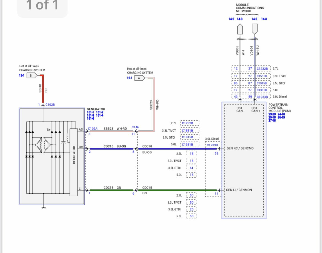
If you're feeling spicy..... It looks like these alternators are indeed externally regulated from the factory, controlled via PCM.
I found an unconfirmed wiring diagram from another forum. Could be a start point for investigating some custom wiring. Looks like GENCMD is a PWM control for field strength. What I'm unclear on is how GENMON works. If it's acting as a 'ground' for the rotor, or if the alt has any sort of internal communication. Again, need to do some investigation on it.
https://f01.justanswer.com/nmwagschal/d3965968-12f0-4239-8ac6-1a9c81501c76_2012_6.7__charging_testing_.pdf

-
Assuming it's a 4s lifepo4 pack, that would put it around 10% SOC.
I'd disconnect it and leave it alone so nothing gets boogered. Normal battery charger won't work on lithium. And the charge profile of a standard alternator (hot/cold voltage or SOC sensing through ground clamp) also isn't a good fit for lithium.
If you're in a bind and you *must* charge it (such as driving without an alternator), monitor it closely and disconnect the charger once the bank reaches 13.4v, which would equate to about 90% SOC. Else if you want to charge it for storage, it's preferred to charge to around 60%, which would be roughly 13.1v.
Of note, it's preferred to avoid mixing battery chemistries -
5 hours ago, MrSkippyJ said:
Do you need it to come back apart?
Yes, but not often
Only for moves and whathave you -
Broken table. Kind of a cool solid 2-pieces-of-wood thing
Top and bottom separated. It was originally held together with a piece of plywood - run some screws into the base to hold the plywood, then run some screws through the plywood to hold the top.
Screws that were in the base came loose over time and the whole thing separated.
Curious if there are any better methods to put 'er back together? I plan on doing some refinishing work while it's apart. Really just needs to be sanded down and polished.
I pondered drilling a hole down the center and running some all-thread + bolts through the base, or doing similar but with threaded inserts into the top to clamp it down; but that feels.... Perhaps overdone?
-
And what sort of power output do you need at a given ohm load?
-
You might want to rephrase your post
We don't allow brand v. brand comparison threads here. Keeping fanboyism to a minimum and what not -
What was your budget?
-
Soundigital has a unit that might offer a similar size / power density envelope
I have no first hand experience with it though
https://soundigitalusa.com/products/800-1-evox/ -
On 7/28/2023 at 9:20 AM, MikeyD said:
That is a ground clamp that Fords BMS system uses. I wasnt sure how to make the transition from 2/0 wire to this small wire.
I did unplug this and it does jump to 13.3 or so but i get the idiot light (which i cant stand :))
I am aware that the LTO isnt great for this but with size requirements not sure i have any other options.
Thank you for the knowledge. I do apprecaite it. Looking forward to more.
LTO is great for this
The charge profile, however, is not
LTO charges CC/CV - alternator holds a voltage and keeps it there. No hot/cold.
You might have luck turning on the headlights too. On some vehicles, it'll boost/lock charge voltage to 14-14.4 or so.
Barring that, you'd want to get an aftermarket alt from mechman or something, but ask for an external regulator and use the dial to set voltage. If you do this, throw the wiring kit out and use 8 gauge to connect the thing. -
2 things:
1. Have you measured the voltage at your alternator with a multi meter?
2. Hard to tell, but in the second pic, is that a ground clamp on the negative terminal? I'm looking at the thing with the plug. If it is, you'll want to route your ground wire through that. Else, you could try unplugging it and see if the vehicle defaults to some other voltage, without the smart charge. That charge algorithm won't work with the LTO batteries anyway -
I'd worry about the 5k amp out-pacing the alternator.
If it's in the budget, I think, dollar for dollar, your best bet would be alternator, front battery, then you could probably get away with a single rear battery if you're running the 5k.
I don't have any experience with those units and if they'd even be able to take the full grunt of a 5k. That said... If you're careful, the 8k would be more apt to provide clean power, but you'd need to exercise some good restraint on the volume knob. -
Probably more effort than it's worth, honestly.
Arm chair refereeing: Not sure that alt would be worth using even if it fit. Large pulley on the front means low idle output (if it even is a HO alt and not a show piece). Front mounted fan is less effective at cooling the rectifier, so it would be more prone to heat issues. Especially with the large pulley spinning it relatively slow - less airflow. -
Sorry to hear
To debug that second battery, I have a couple questions for ya
1. What orientation was the battery in?
2. What's your charge voltage both when you first start the car, then again after ~30 minues?
3. Details on your vehicle? Alternator, wiring, amps, batteries, are what I'm after -
On 1/21/2023 at 1:25 PM, LoudFiat said:
Hey guys, I'm the owner of LoudFiat. I'm working on my own high voltage amplifier and releasing my own HV products. AMA
More info at http://www.LoudFiat.com
That's kick ass dude!!
On a scale of 1 to pucker, how was it tapping into the HV battery? Does the vehicle's controller throw a fit from the unaccounted power draw?
How about the other general logistics? I imagine it's difficult to find wiring/relays/meters/etc rated for that sort of voltage

Random Picture Post V2
in Off Topic - Random, Misc posts - the forum "Junk Drawer"
Posted