
.jpeg.eead499019769cdeefc4241afe600f9b.jpeg)
Ecohostile
-
Posts
31 -
Joined
-
Last visited
-
Days Won
3
Content Type
Profiles
Forums
Events
Media Demo
Store
Collections
Videos
Posts posted by Ecohostile
-
-
On 3/2/2024 at 11:53 AM, CstrokerV said:
a Cap bank will help, with not having a good alt
I'm definitely wanting to look into that. I may try and use half the lithium I have or just wire it up and see what happens. If I end up going the cap route, I'll need to do some research.
-
Sorry I've been MIA. As for the 74AH pro I'm not sure you should get it. I'm second guessing my purchase already and I cant send it back. I'm still going to try and use it but i wish I would have done more research. Apparently these cells have a really narrow voltage range. It might work for me but I'm still a ways off from testing them out.
----------------UPDATE 2/25/24---------
I decided to revamp my system entirely. I sold everything from my old car except 2 SA x-8's, my SIA2500.1d, and my wiring.
I got rid of my Infinity Kappa 3-ways and purchased Infinity Kappa Perfect 3-ways. The new setup is as follows
Helix M Four DSP running my tweets and Midrange
2 Sound Digital 800.4's running my midbass, center channel, and rear speakers
SIA2500.1d running 2 SA X-8v.4's - 2ohm's @ 2000watts
- Also contemplating building a T-line enclosure for these
Also I decided to do custom a-pillars. So on with that!
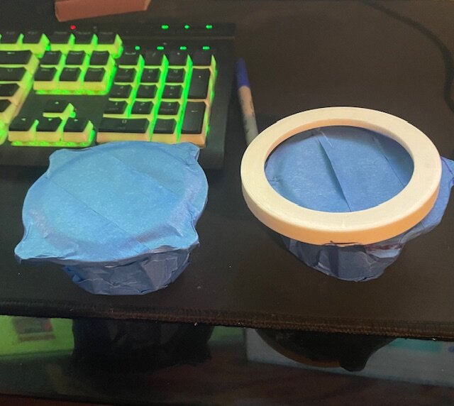
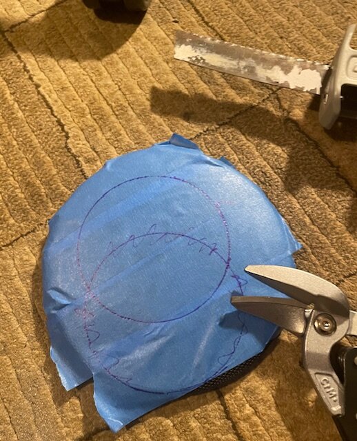
These are my Infinity Kappa 300m midranges all taped up and ready to be trimmed. The two things i dislike about these are that the mounting tabs add an inch of width and they don't come with grills. Gonna have to fix that.

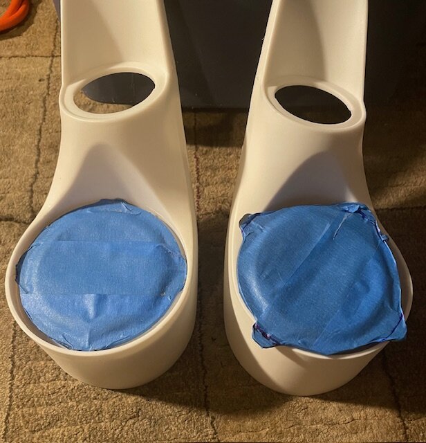
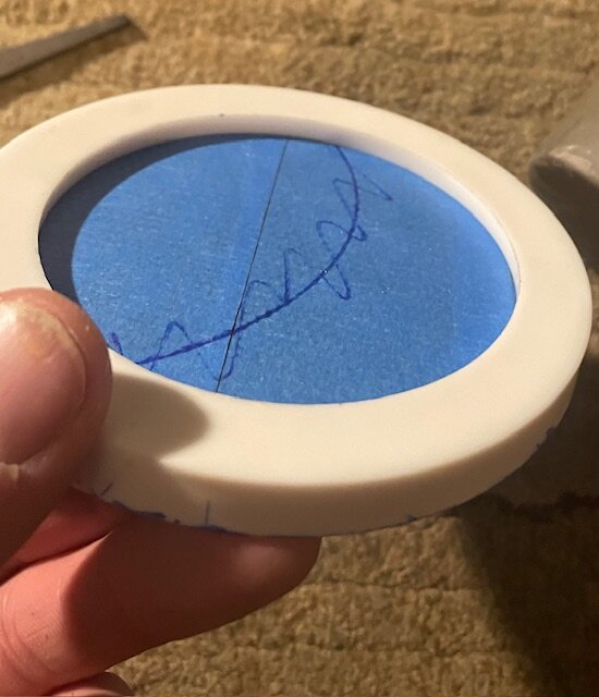
Left one trimmed, on the right you can see the problem. These are some funky a pillar pods I found on amazon. I'll still need to do some fiberglassing and trimming once my second set of a-pillars come in. Not gonna modify the originals.
Thank you skar audio for the sacrificial grill
Fit's but is not done.
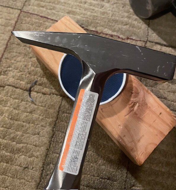
This is a tinner's hammer hammer. Time to shape some metal
Not perfect but you can see what I'm going for.
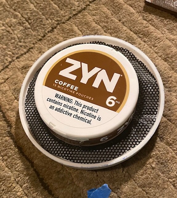
A can of zyn fit's nicely to help with the shaping
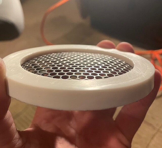
Also had some steel round mesh from another project So I decided to try that as well
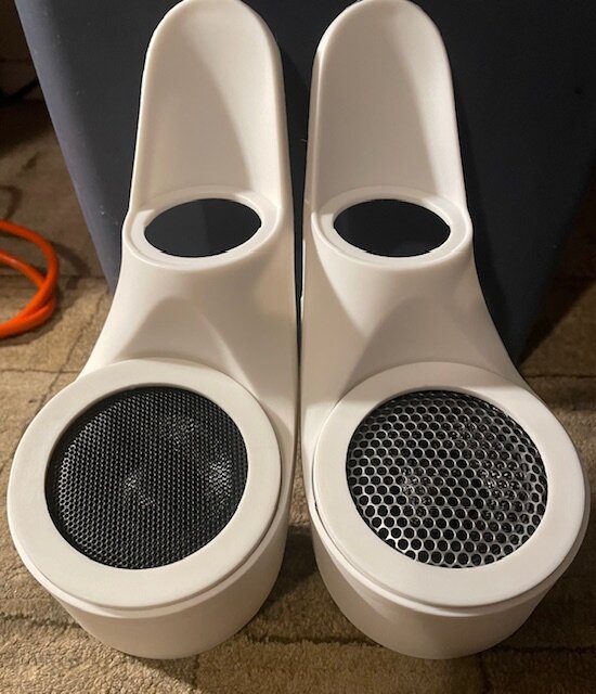
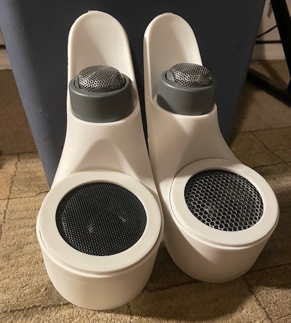
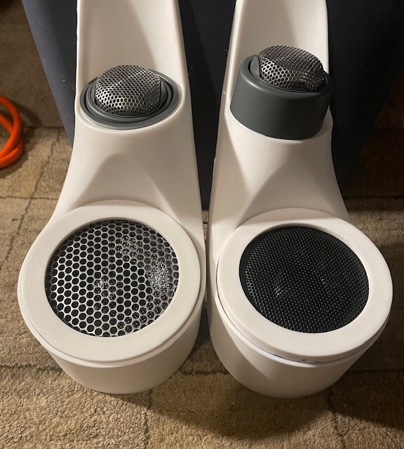
Side - by - side of the two grill options
Now for the tweeters. The flush mounts we too big so originally I was going to use these. But it looks hideous and bug-eyed.
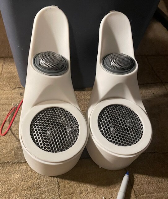
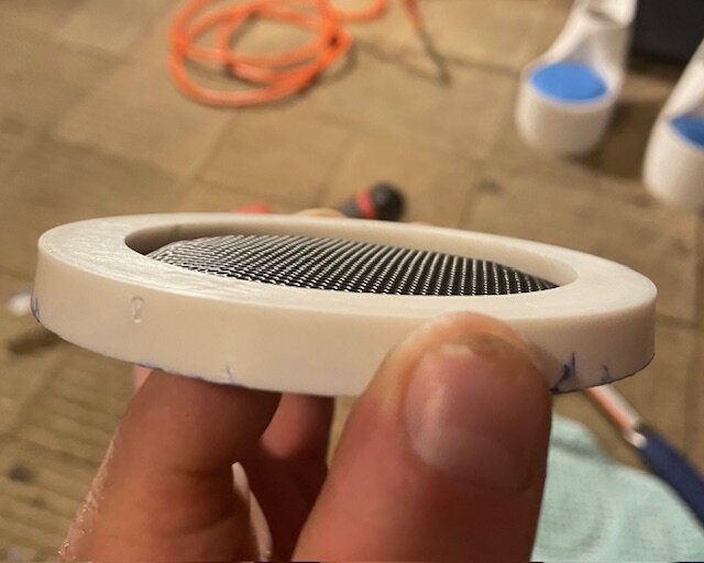
So I trimmed one of the flush-mounts to fit.
And ditched the black grill. The steel looks better imo, especially when matching the tweeter. There's still a lot I need to do to these. Currently the grill is sitting on the midrange surround so I need to fix that, and the pods still need to be fiber glassed to the a-pillars and covered with some kid of material. But that is for another day.

-
 2
2
-
-
LITHIUM Update!
So the guy who runs JAG35 finally got back to me and gave me the green light to separate the cells from the lithium bank and chop the PCB in half. I was pretty confident that this was possible but it's always good to double check when you're messing with lithium.
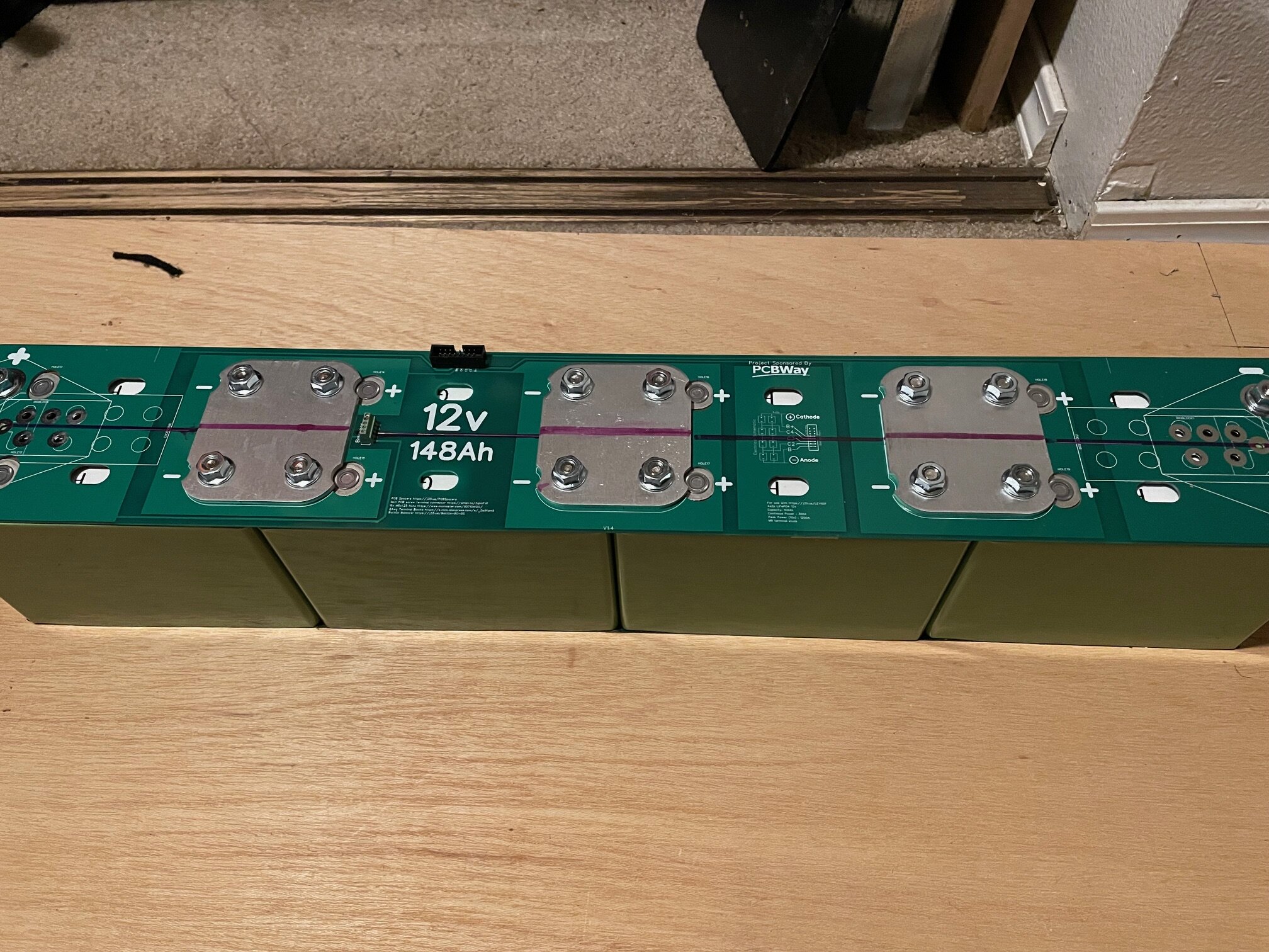
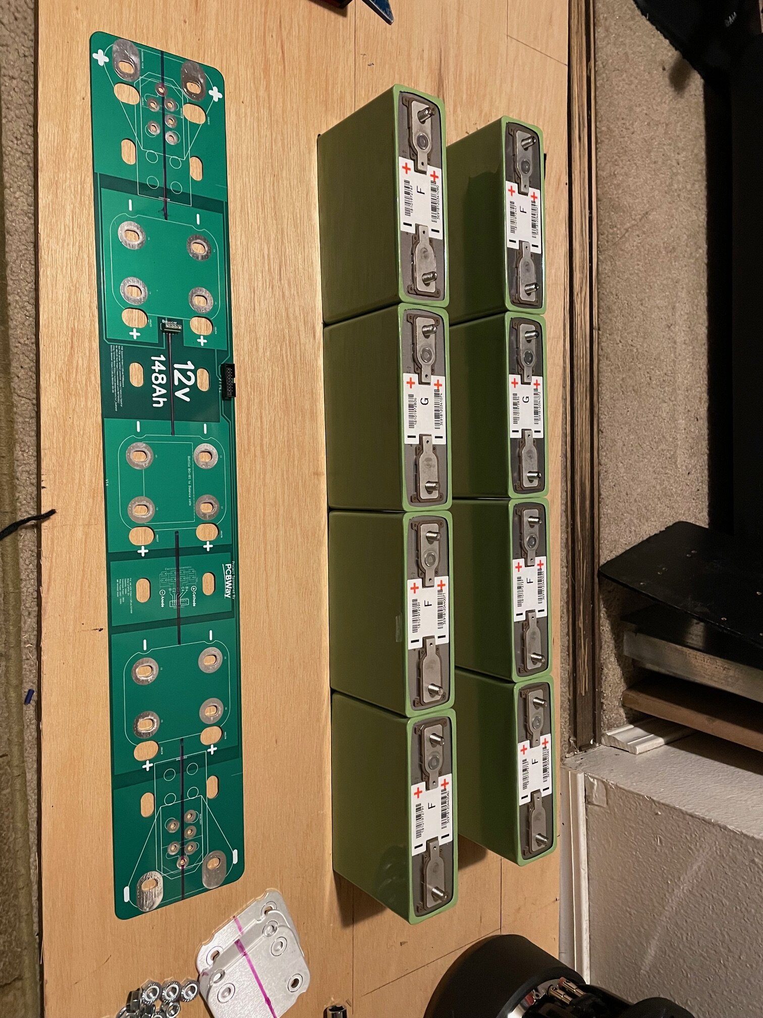
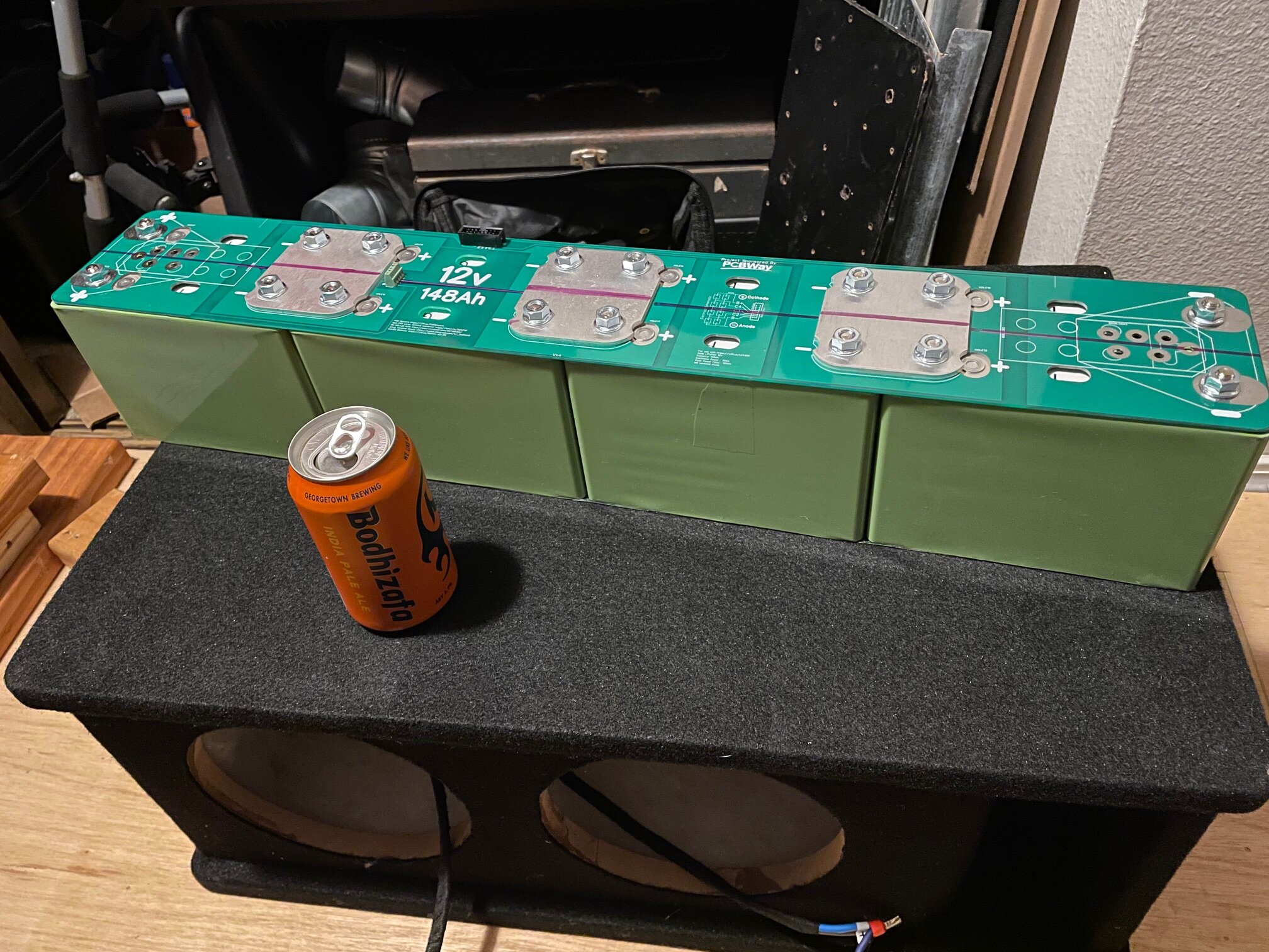
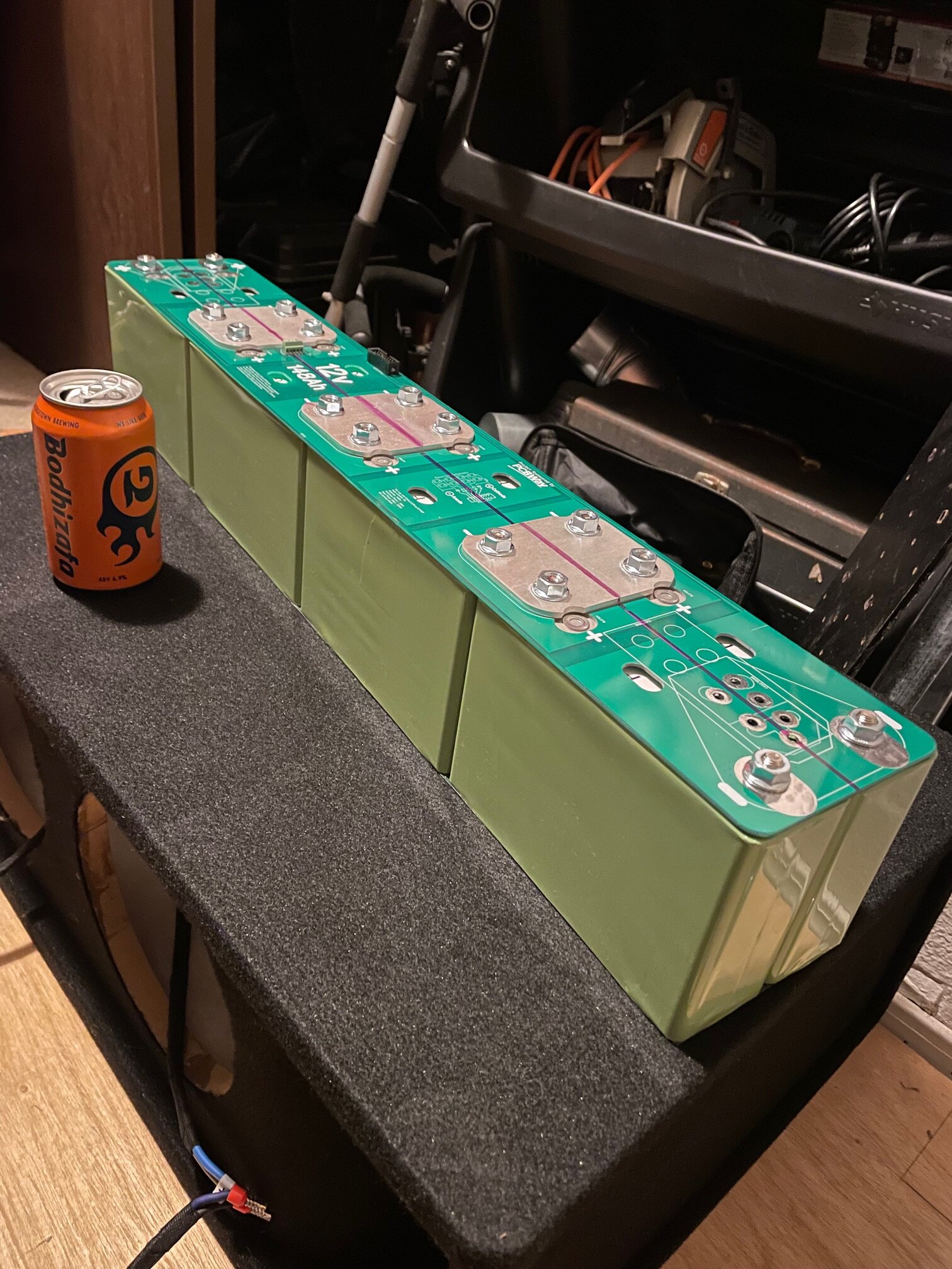
The cells I'm using are LEV60F Prismatic by Lithium Energy Japan. They have a nominal voltage of 3.2-3.5 or 12.8-14v when run in a series. When running 8 cells total I should have a capacity of 148ah with 1200a of burst power and 800a continuous or 600a/400a if I decide to run half. In watts that's 14,400w burst and 9600w continuous.
I know this is overkill but I'd rather have too much and room to grow, than not enough. And it's beginning to look like upgrading the alternator is out of the question for my car.
On to the pictures
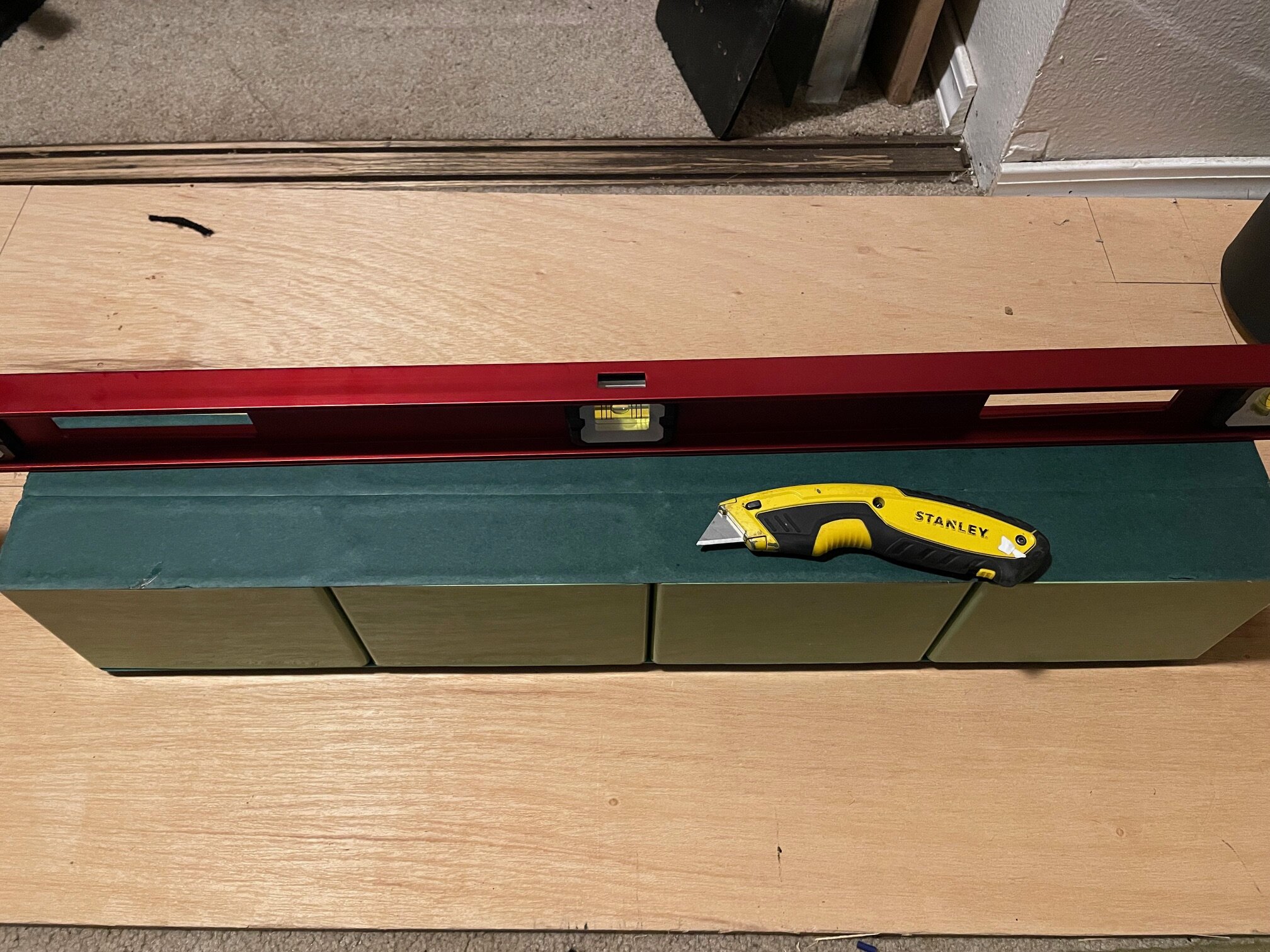
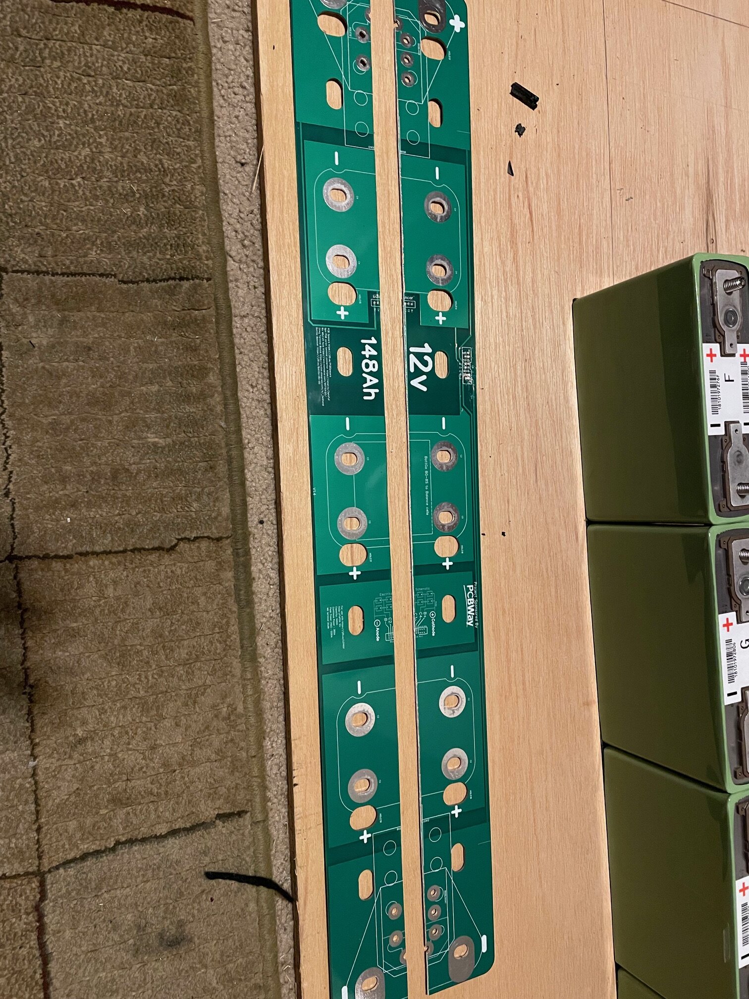
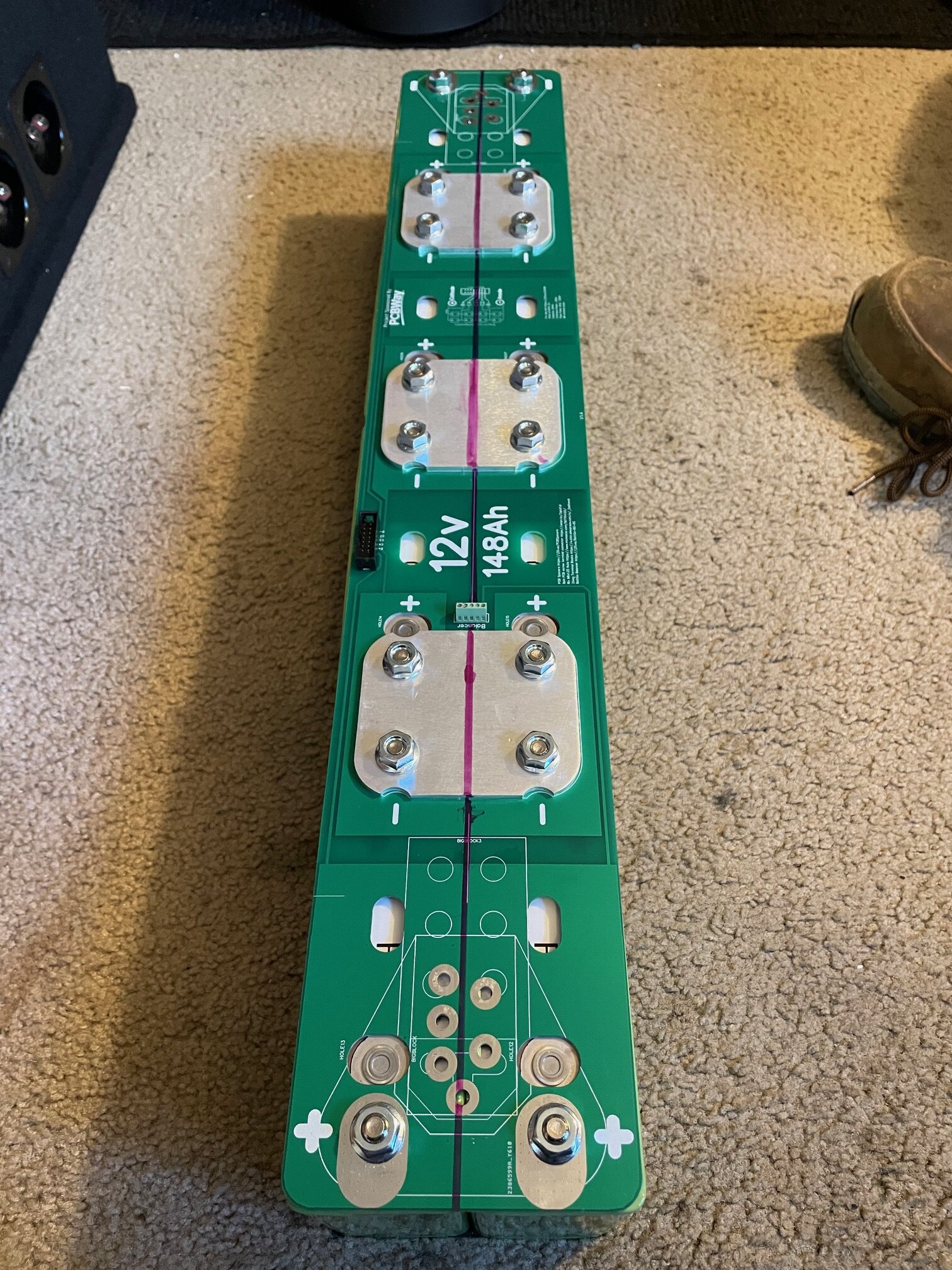
Marked is how I want to separate the cells.
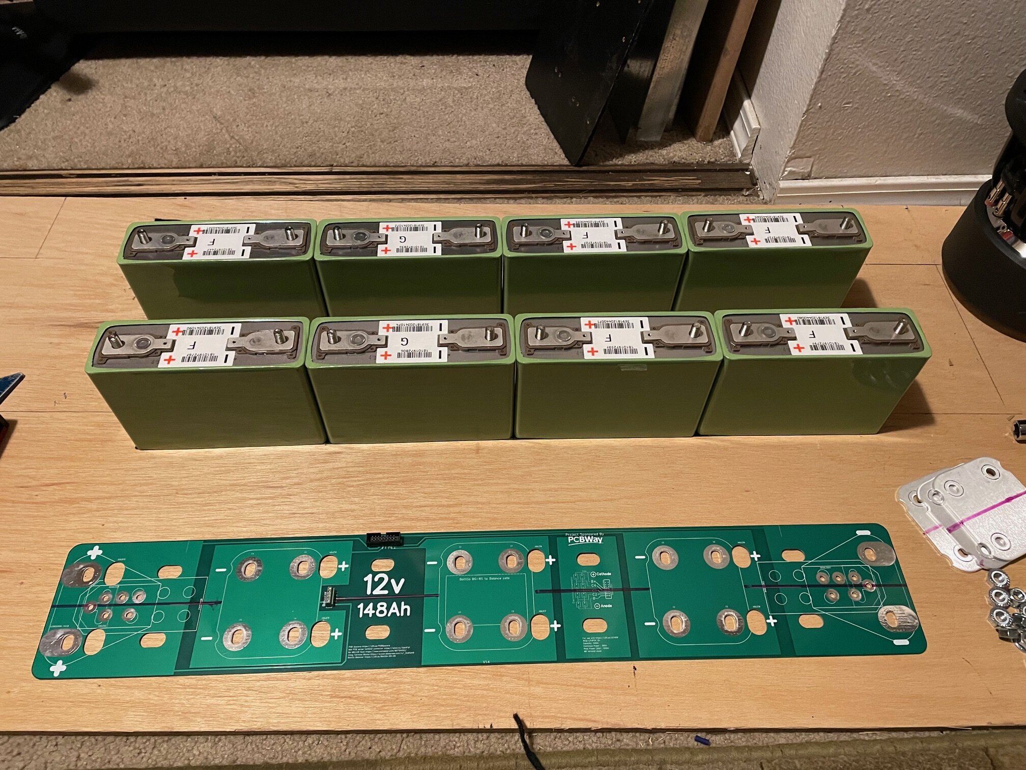
And here's the underside taped together with fish tape
Very carefully I cut the tape in between the cells with a box cutter and a straight edge
Next I removed the 1/2" bolts and the PCB
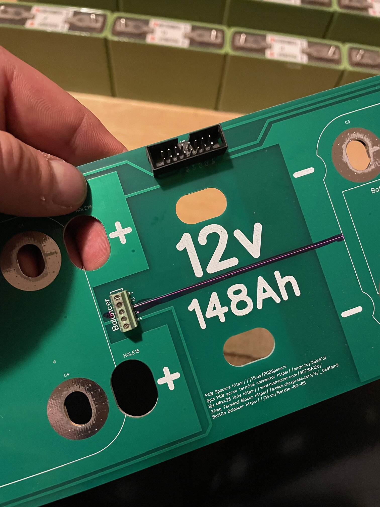
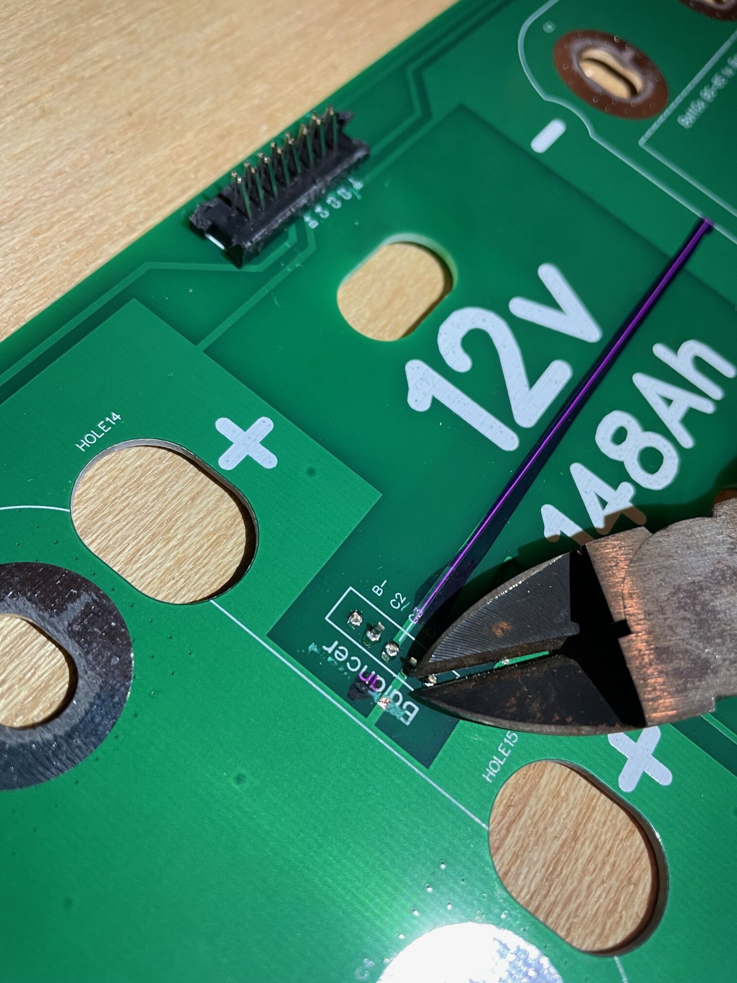
Next I needed to get rid of these connection Ports. They're for monitoring/balancing the cells, which is unnecessary for this application.
A pair of dykes will do the trick but you'll want to watch out for shrapnel
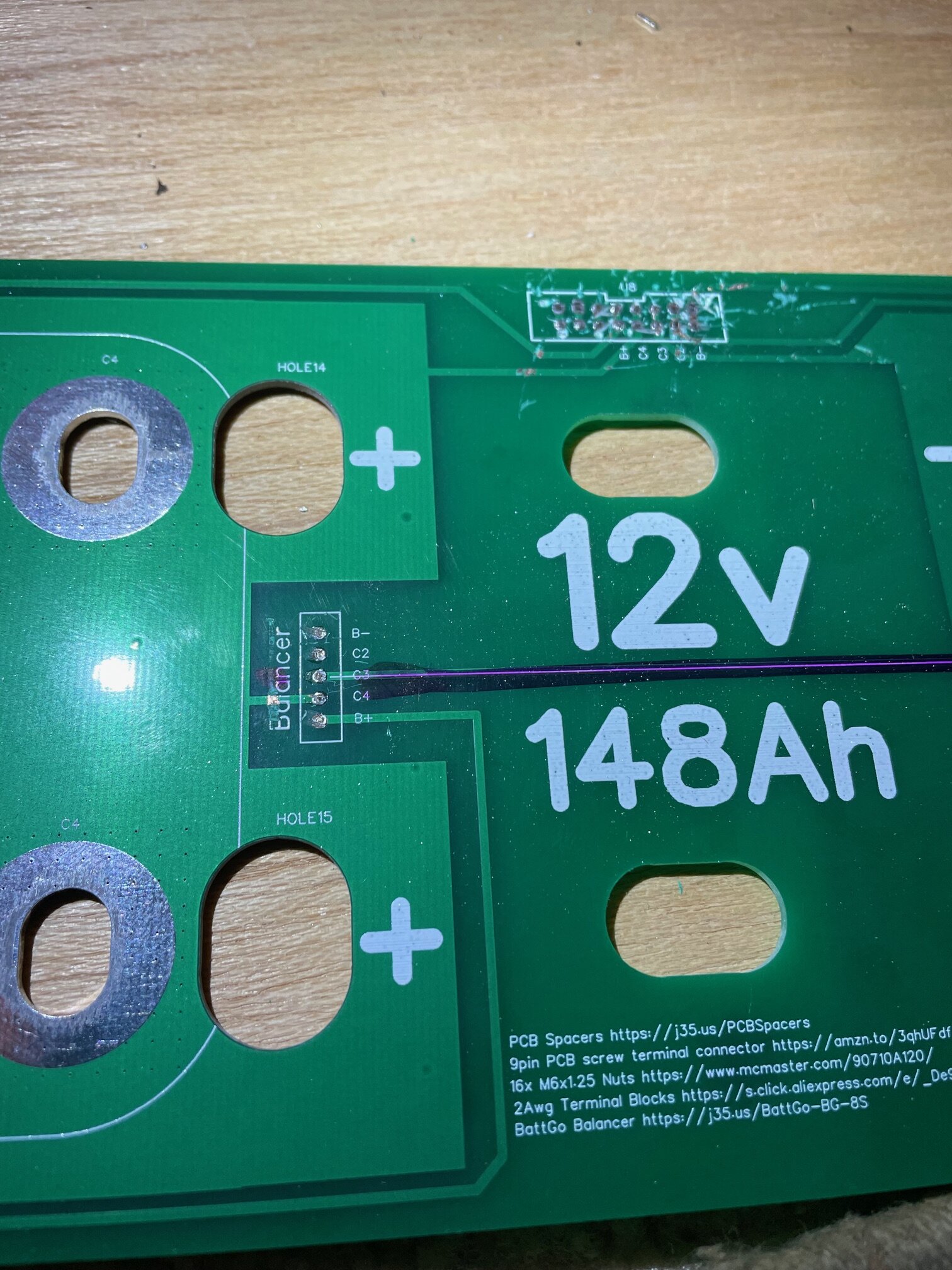
All clean, I hit these lightly with a Dremel just to clean up the sharp edges. A better way would have been to de-solder them but I don't have a soldering gun.
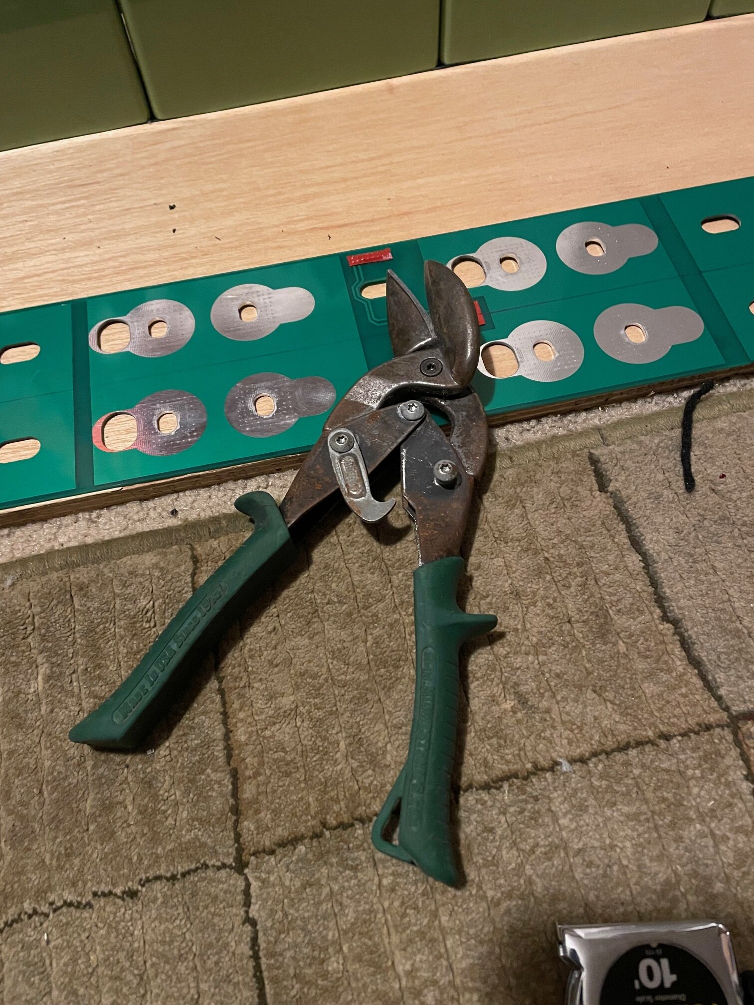
After remarking Center with a flat PCB ( 2 - 5/32" WTF lol) I used a pair of tin snips to cut the PCB. This is By far the best way to do this. There can be some pretty nasty chemicals in PCB's that you really don't want to breath. Also your cut will be nice and straight.
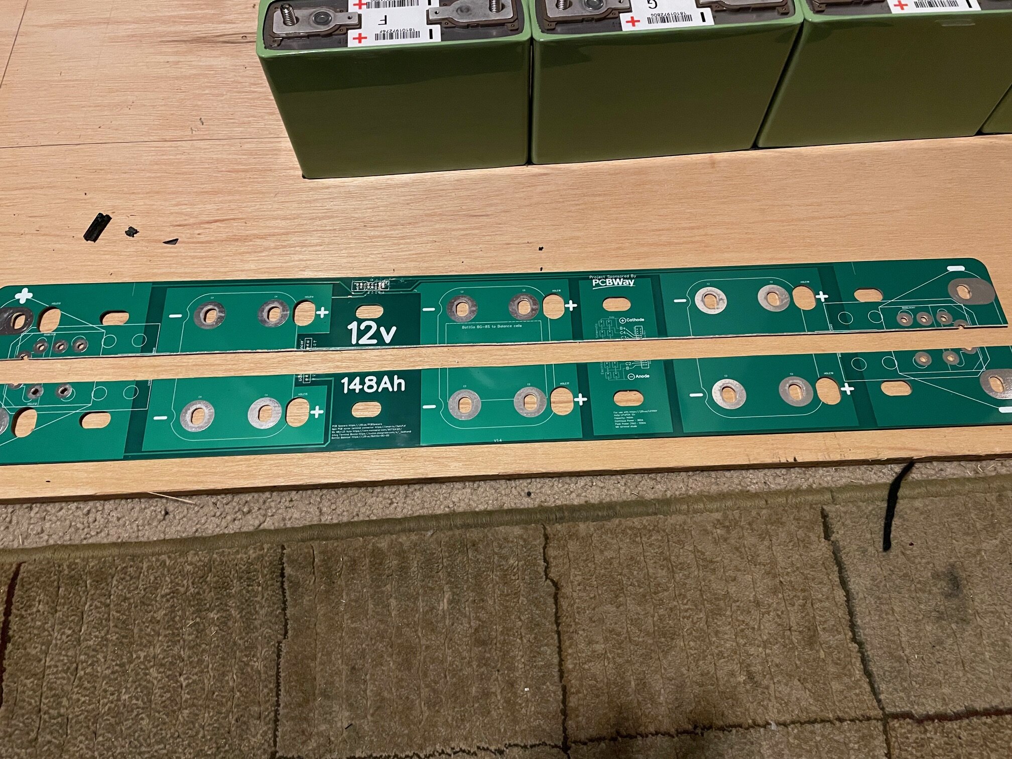
After cutting, I copied the rounded edges from each half onto the other and ground them down with a Dremel ( I know I just told you not to do this.) This way the corners wont stick out past the cells, and it looks nicer.
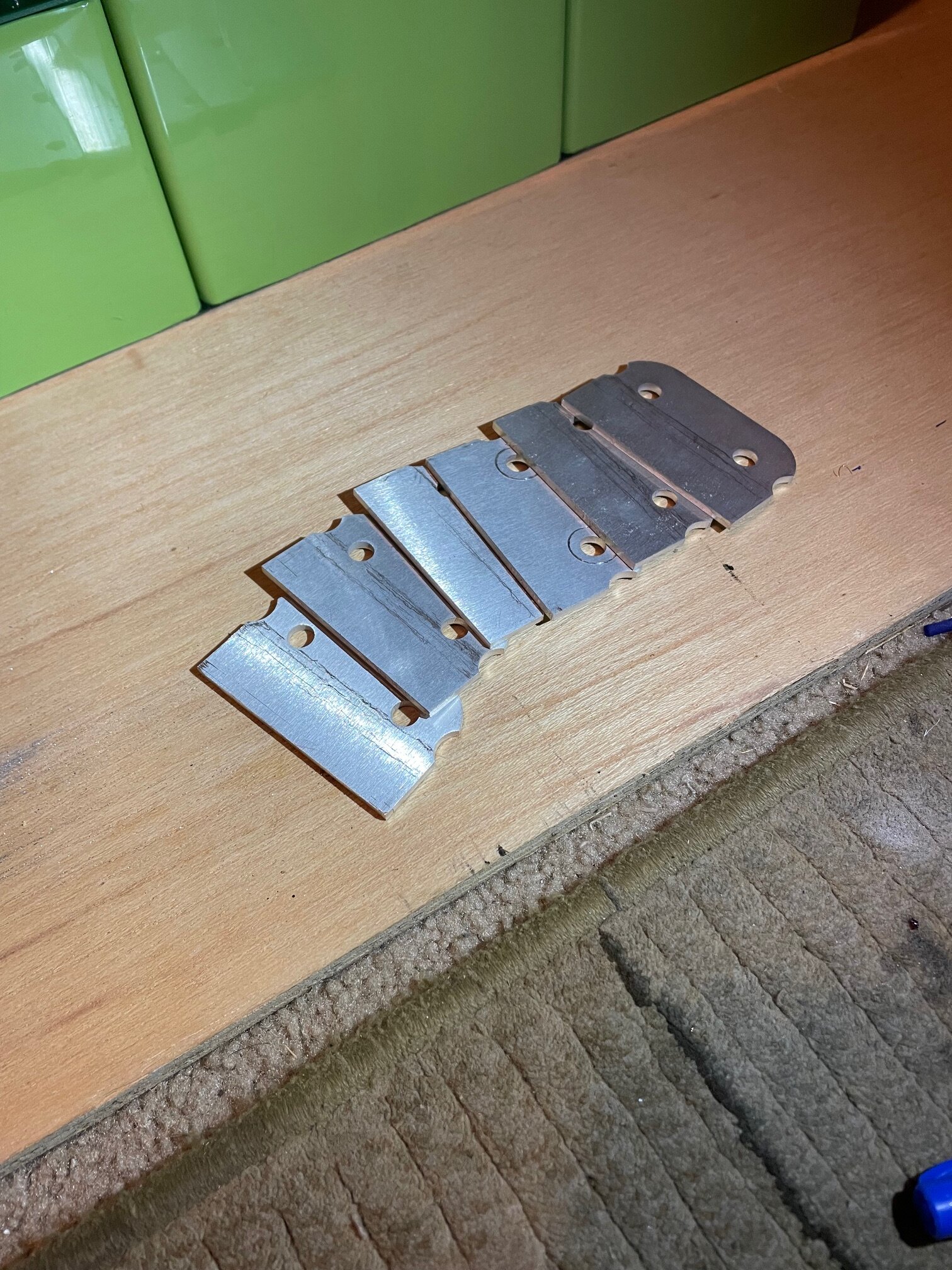
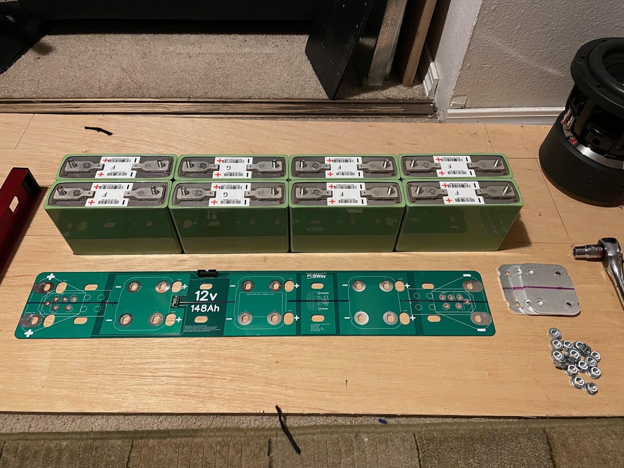
Next I chopped the Bus bars in half. These are 1/8th thick aluminum so I used a bandsaw. You'll want to make sure you get the orientation right as the holes are different distances depending on the orientation and if you mess up then you're now making your own because you cant order them as far as I know.
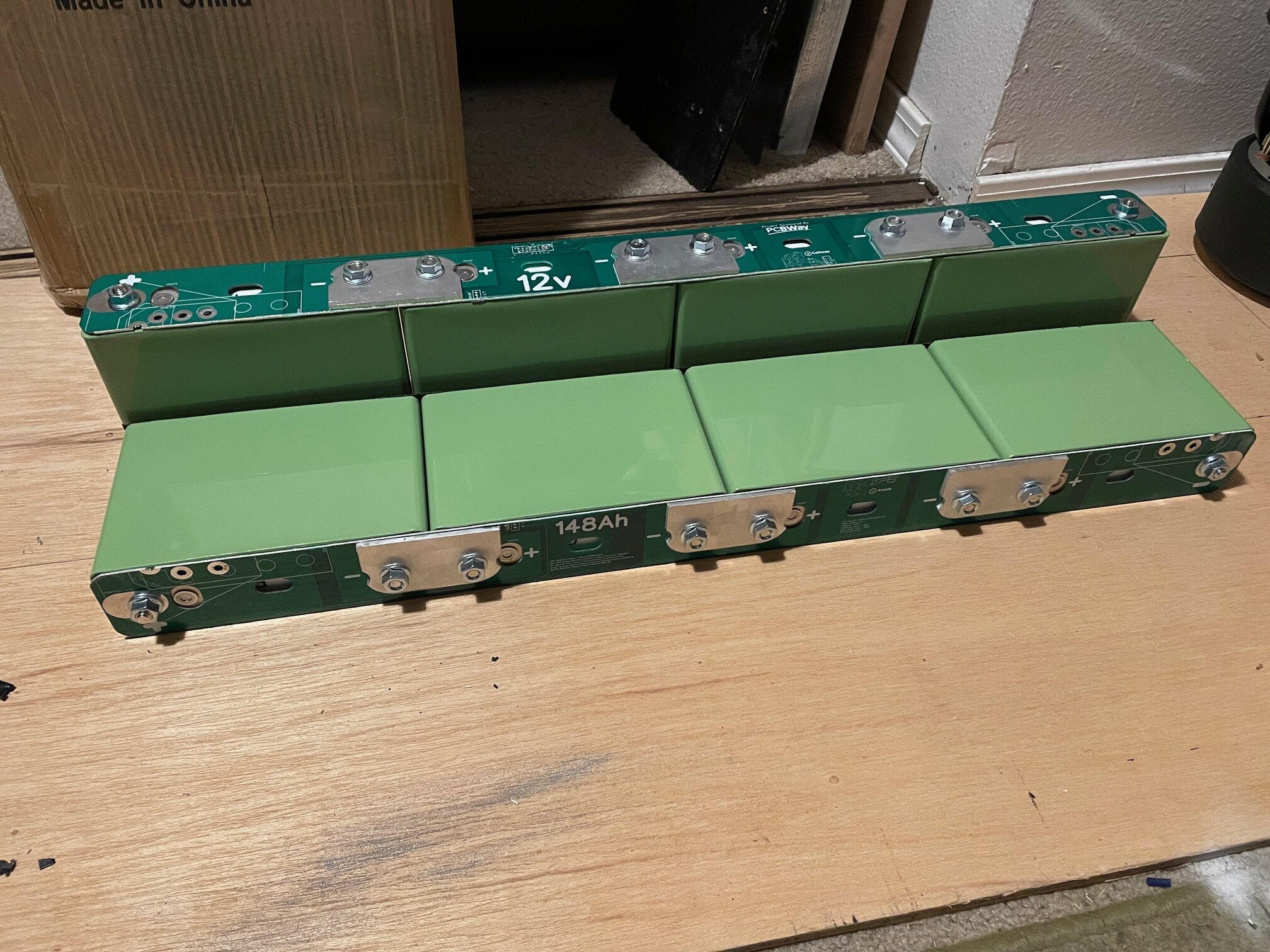
Reassembled the cells, making sure not to overtighten the nuts. The torque rating for these bolt is only 6.64ft-lbs which is not very much. It would be very easy to over tighten and damage these cells.
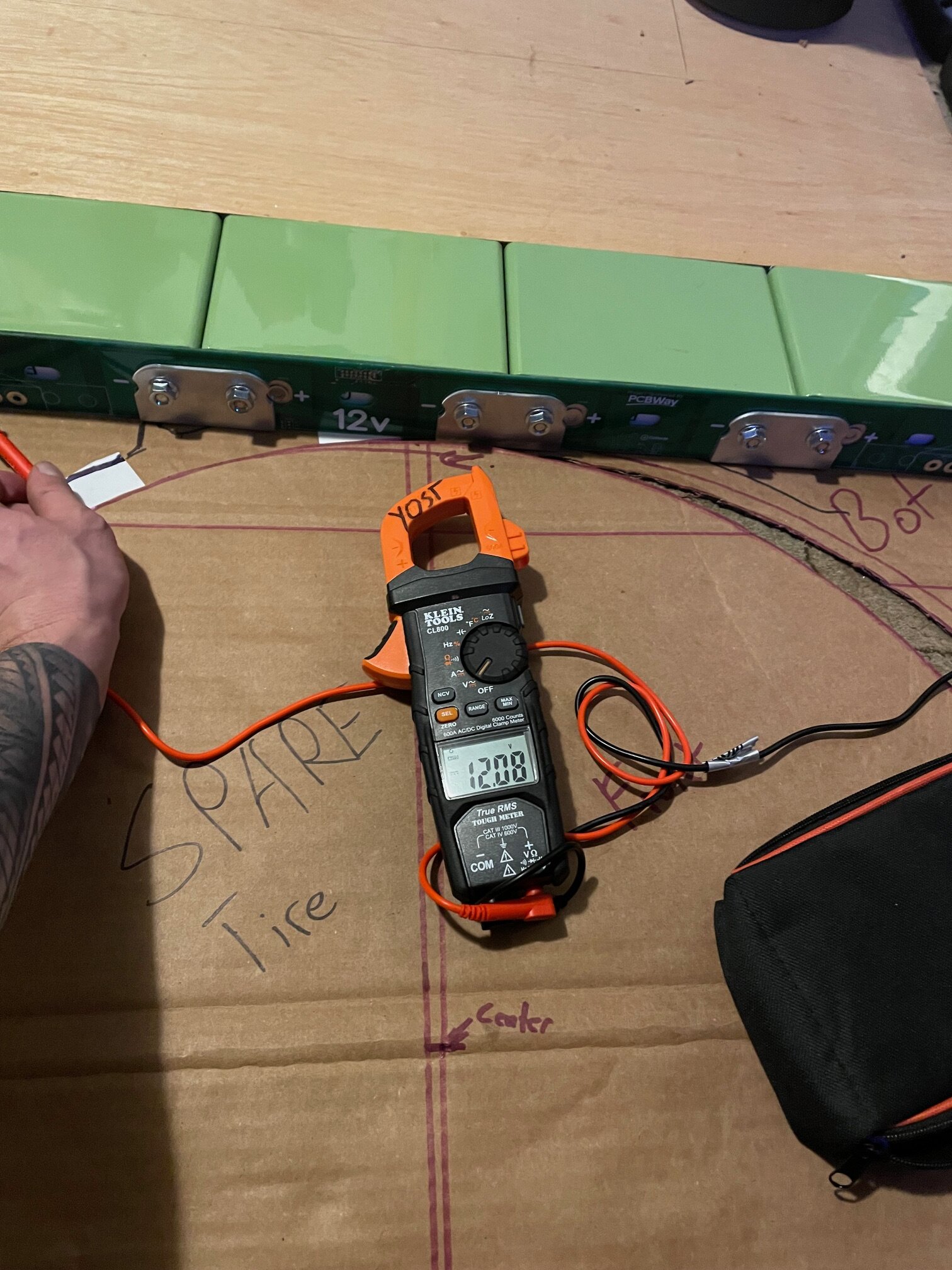
Checked the voltage and both came out to 12.8v which is the same as before. I still haven't charged them yet. When I do I'll be looking for 13.2 before I wire them in.
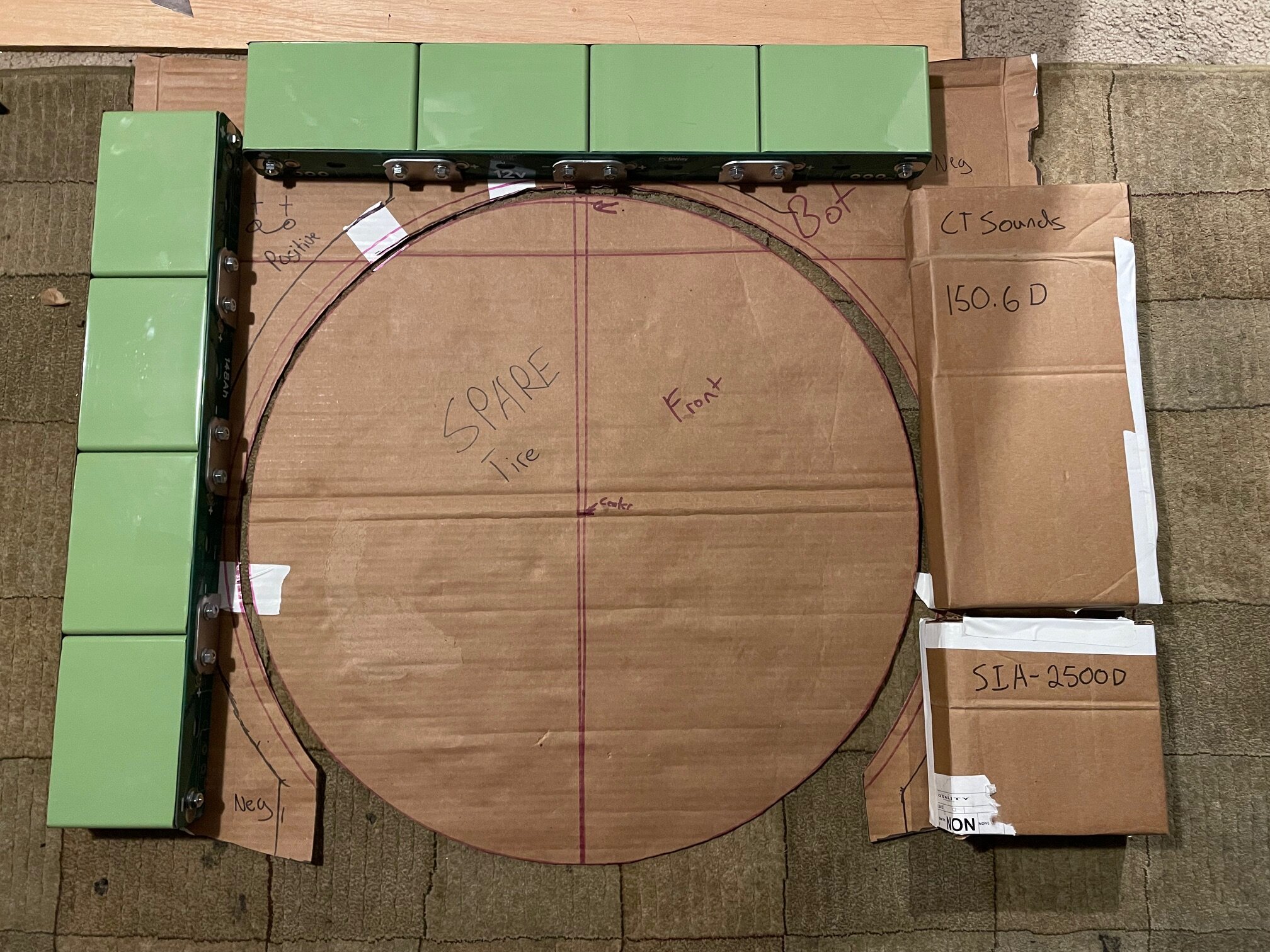
And lastly this is a mock-up of how I would like to lay them out in my trunk. It's tight, but I should be able to fit everything with a little bit of modification of the rear inner quarter Panels. The goal is to have everything 100% hidden while retaining my spare tire/tools. Also I'll be constructing everything in a way that can be reversed when I sell the car down the line.
I still need to make some compression plates to prevent the cells from bulging, but those will be integrated into the amp/battery rack. So that's a project for another day.
-
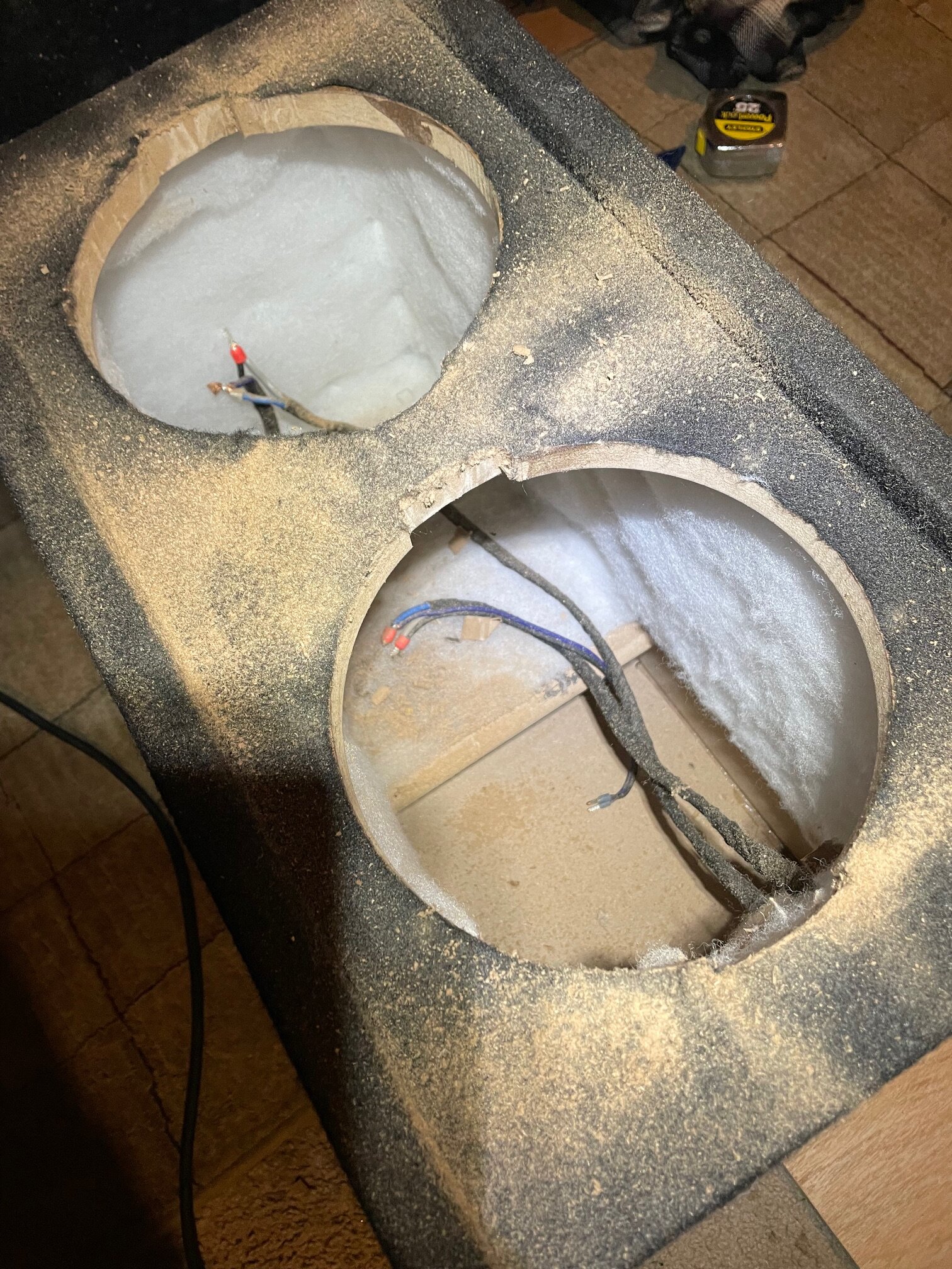
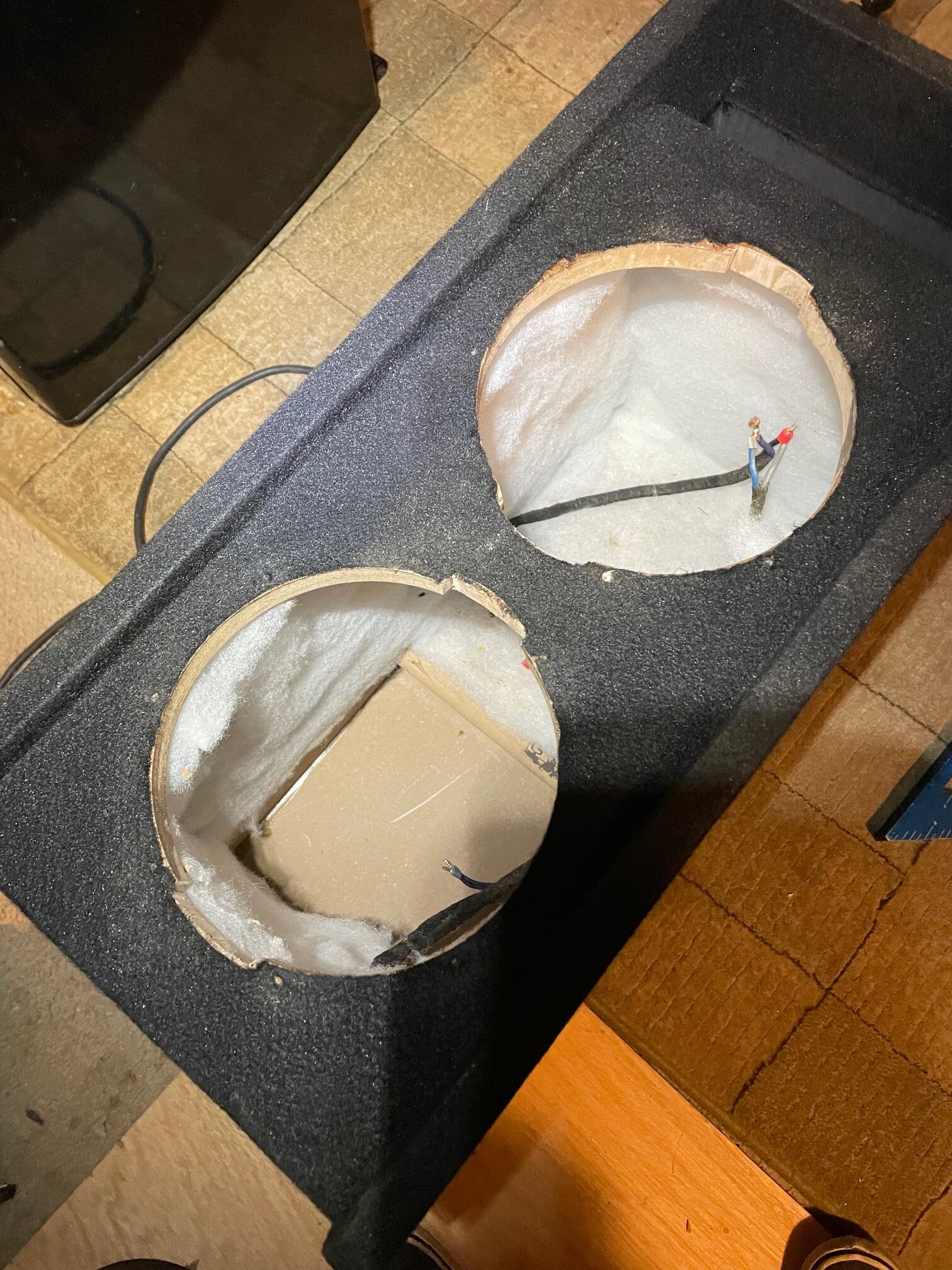
Finally got some screws so I could throw the subs in the box and see how it fits in my car.
First issue I noticed is that the terminals + wire was too difficult to get into the box without ripping the wires out. So a couple quick relief cuts were needed.
Then I hit it with the shop vac.
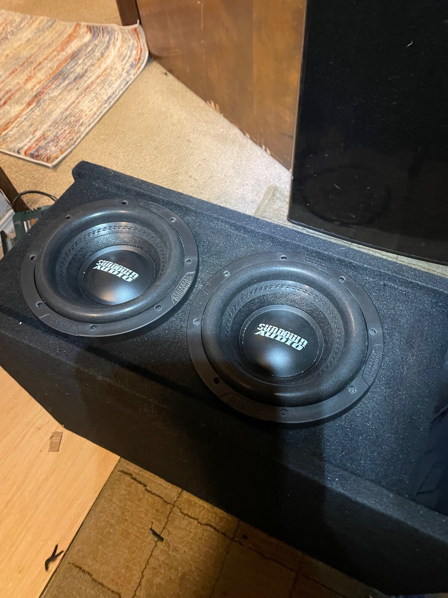
After that, I wired in the subs and chucked em in the box. I pre-drilled some pilot holes and screwed them in. They're snug but not fully tightened yet. I have an idea to make the box a little prettier so they'll probably come out at least once more.
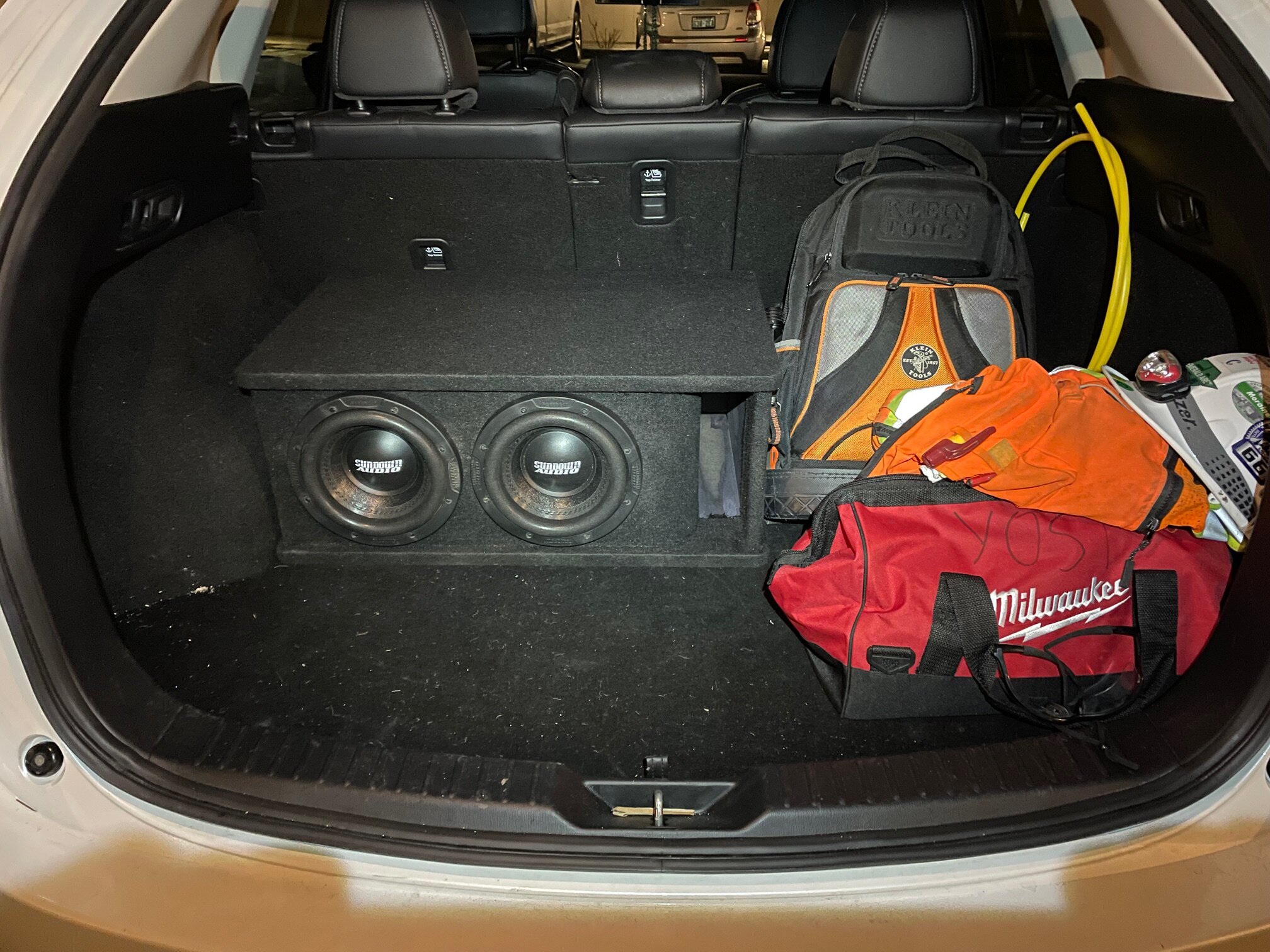
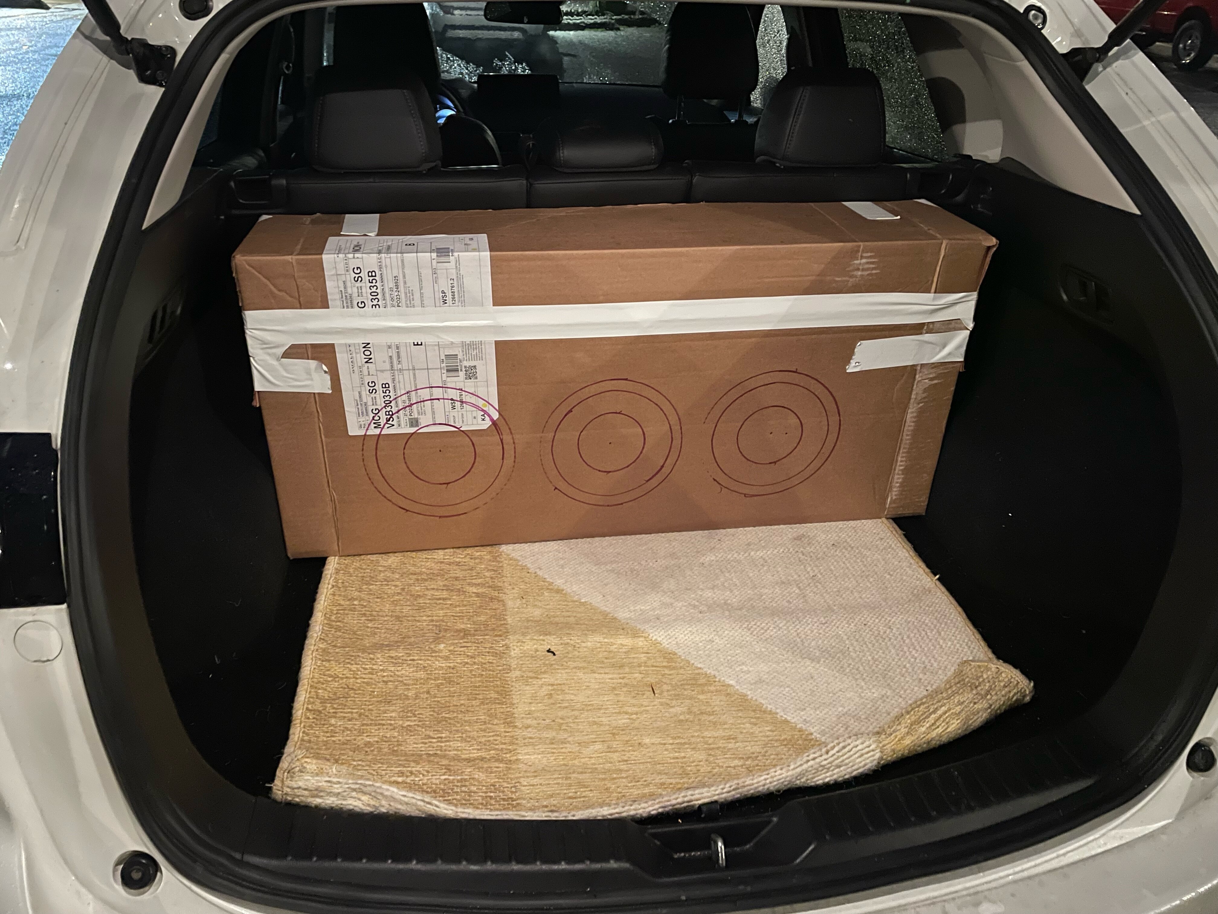
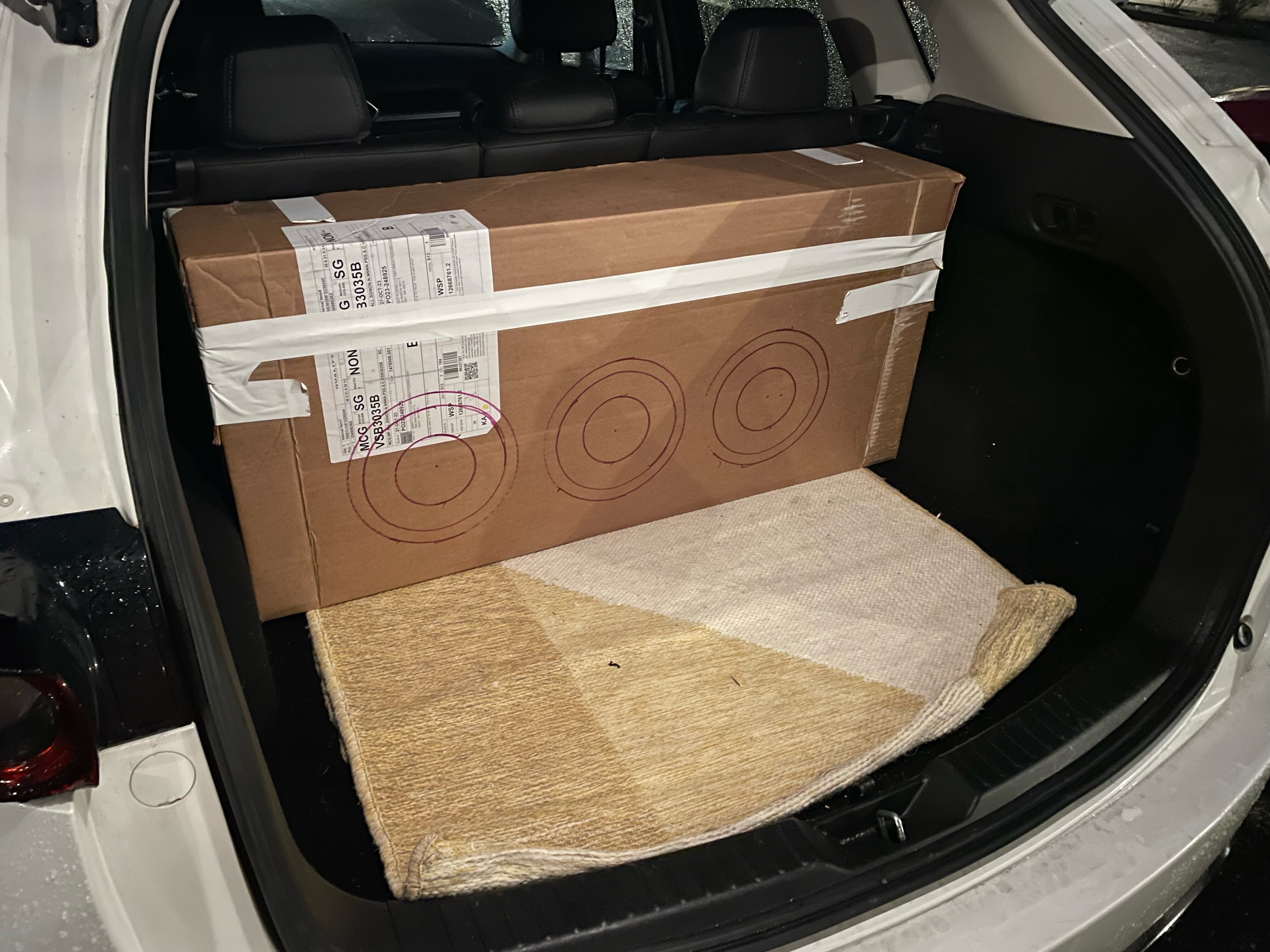
And lastly just a quick test in the car. I'm gonna drive around with them for a few days to see how the space effects me. This is the average load I have in the trunk with my tool backpack, a set of rain gear, and the Milwaukee bag full of drills. Sometimes I carpool so you can just about double that for those days. I'll need to figure out something to protect the subs. Finding grills would be difficult with how much xmax these guys have. Maybe some bars or something. Shoot me any products or ideas you guys have.
I'm also thinking about adding some kind of small lip to the top of the box so I could throw My toolbags on top of the box and not worry about them sliding off. Maybe some kind of cargo net. who knows.
And DEFINITELY glad I'm going with 2 subs now. This box loaded is a back breaker. I May throw some straps on top to make it easier to pull in and out. 3 subs would almost require two people.
-
1
-
-
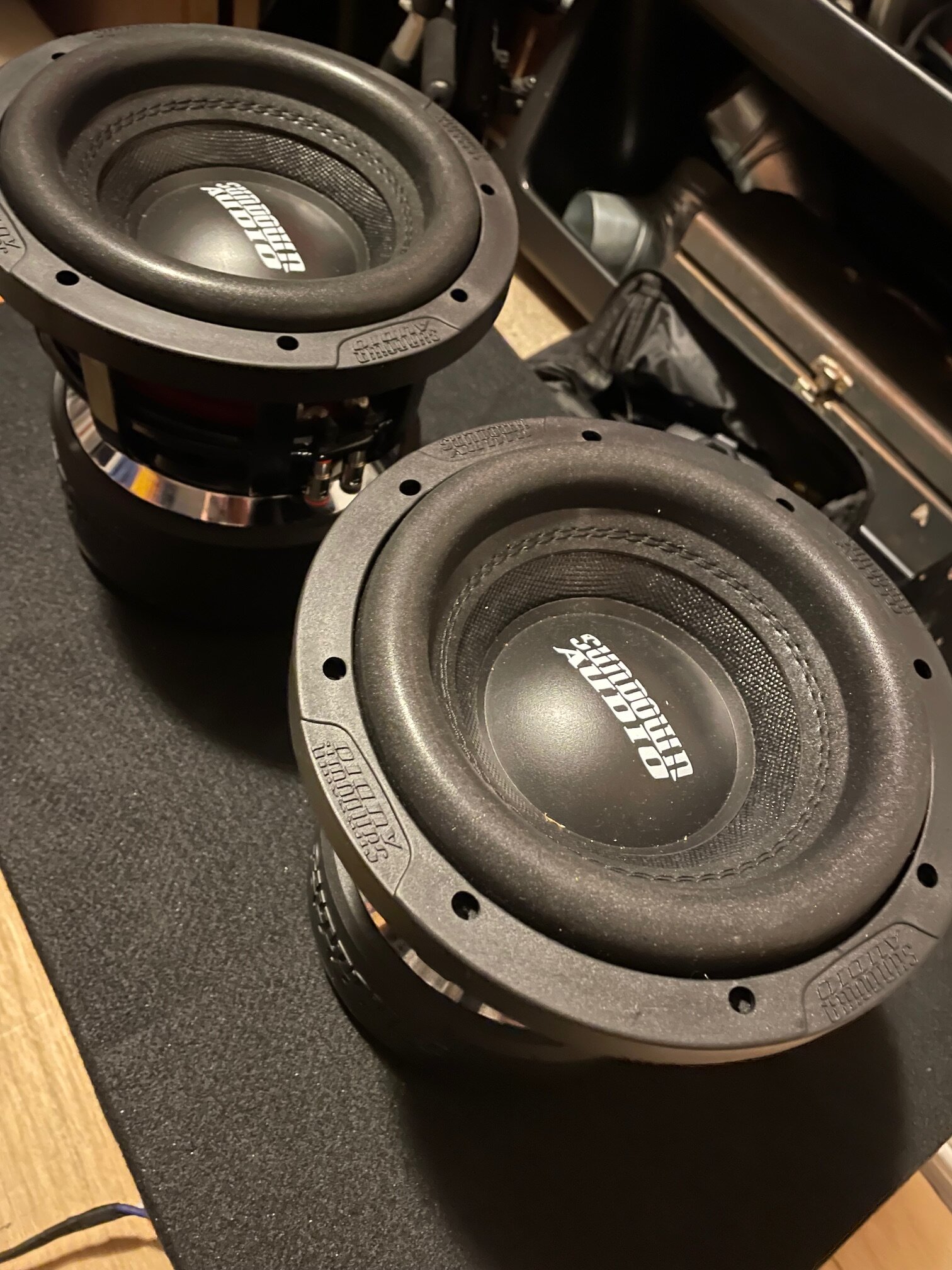
Alright now for the fun stuff.
For subs I'm going with 2 Sundown audio x-8v.4's. Why? because 8's are Rad, and I'm trying to keep my care as usable as possible. But also because it's different. The original plan was 3 but I was having difficulty making a box for three that would work within my size constraints and the SA 2500.1 D would struggle to run 3. Maybe down the line I'll go for broke and run 4 off of a beefy 4k for shits and giggles, but most likely I'll sell off the extra 8.
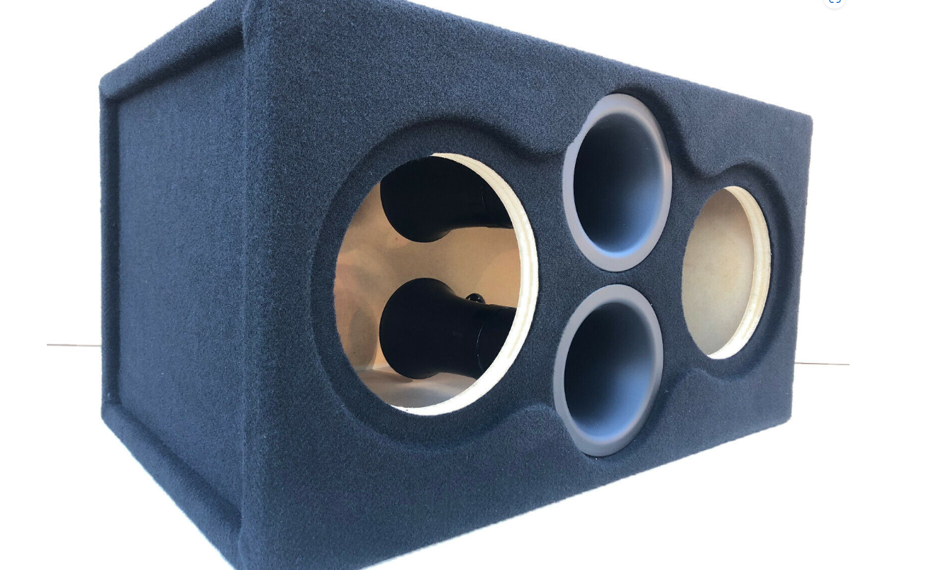
The Box that the subs are sitting on is a CT Sounds dual 8 enclosure with 3/4 MDF, a kerf port tuned to 39hz, and abou .81cu ft per woofer. It's on the smaller side but it was cheap and I figured it would be good to compare against a future box with a full 1cu ft per woofer and 32hz tuning. But first, I needed to fix a few things.
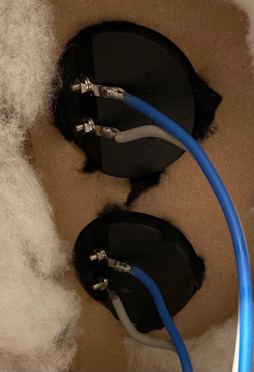
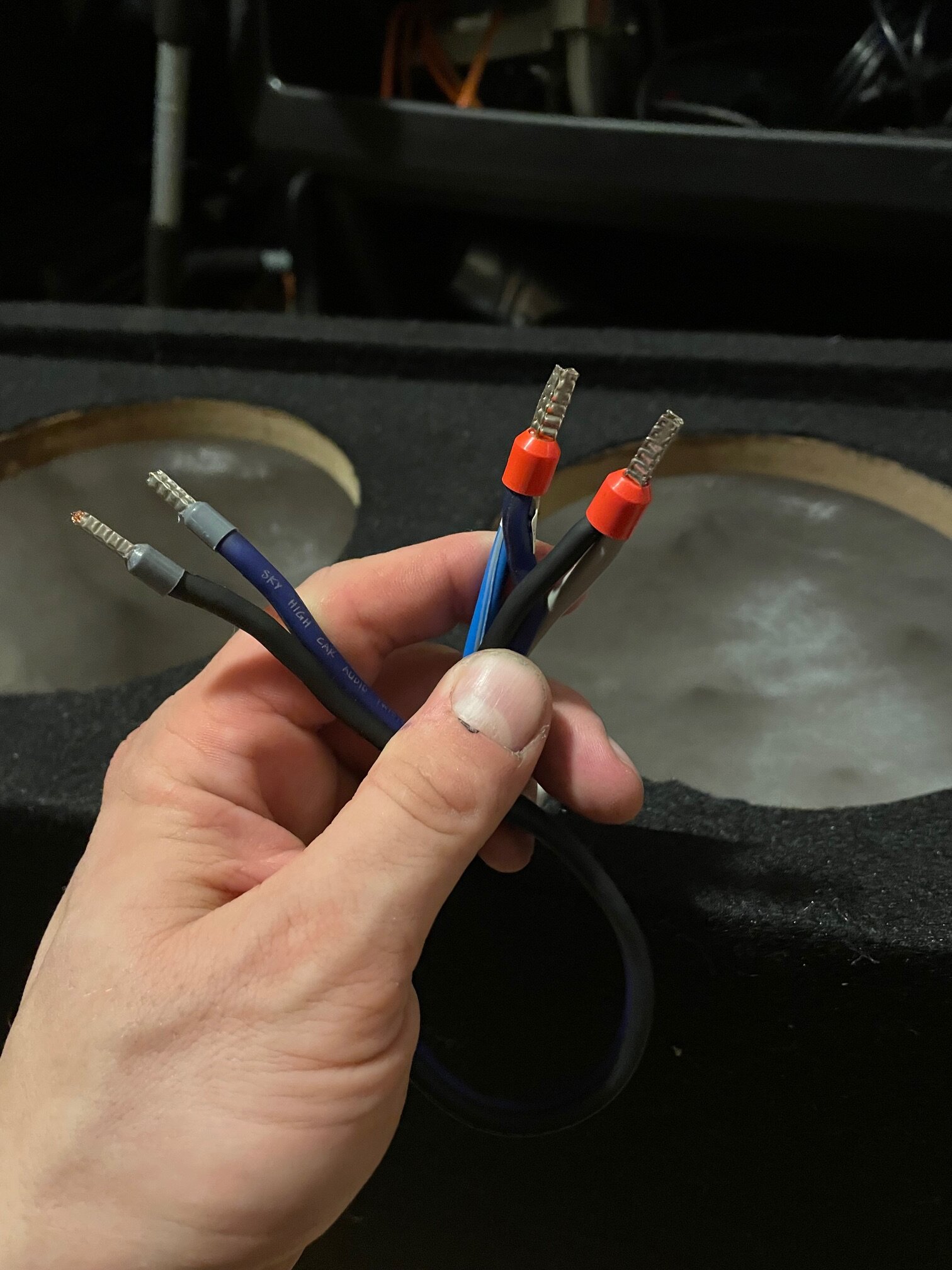
These Cup terminals. Known for being leaky, So lets fix that.
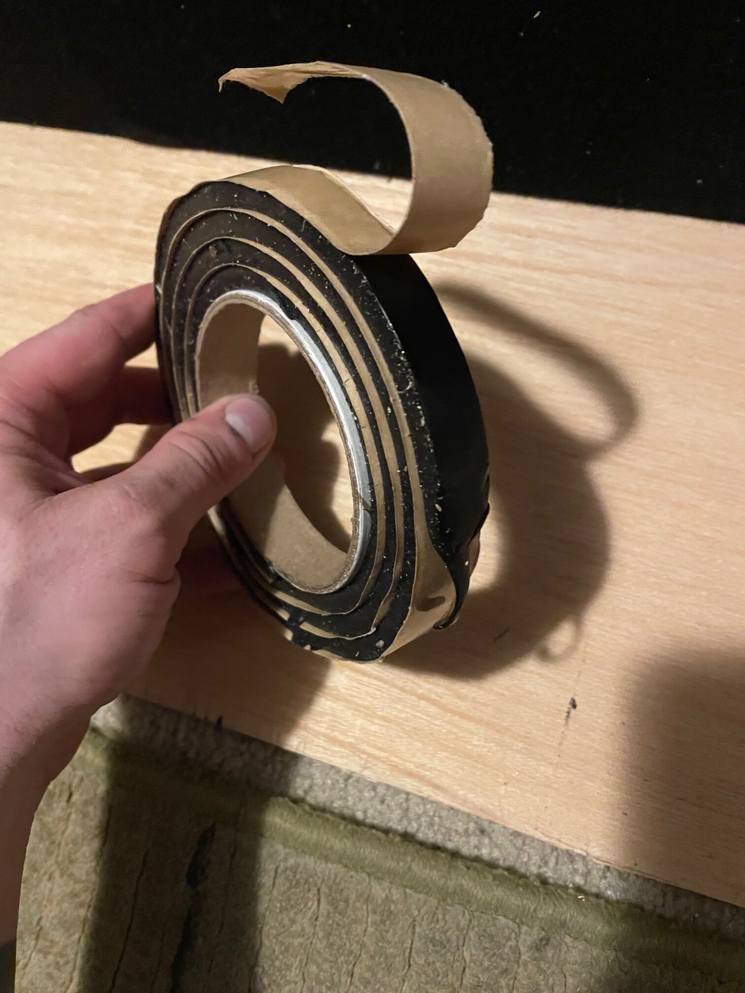
This is some Second Skin Butyl Rope that I had leftover from my last build. This stuff rocks. It's especially good at silencing license plates.
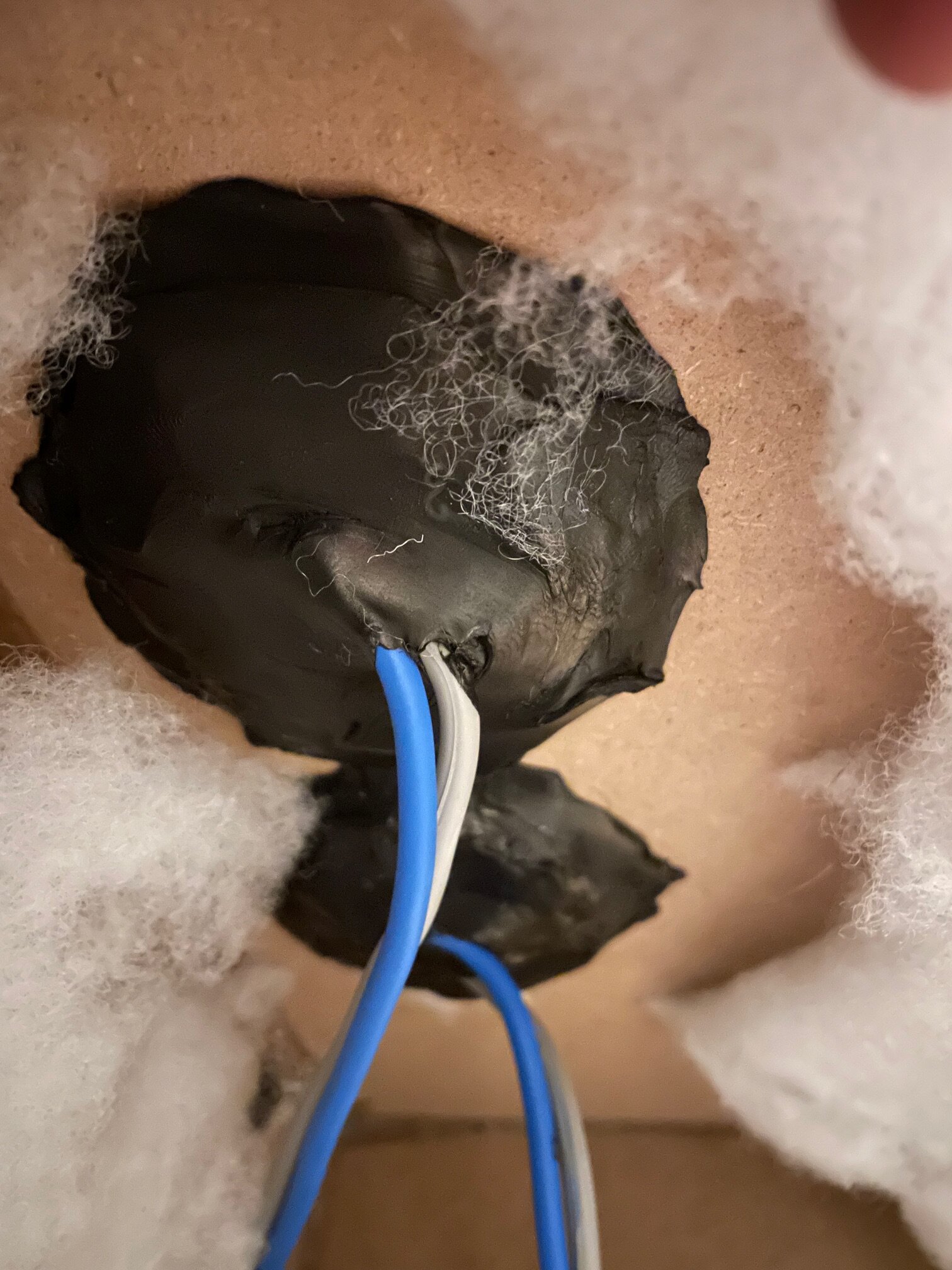
This worked for me before with a sealed enclosure, just gotta really work it into the cracks.
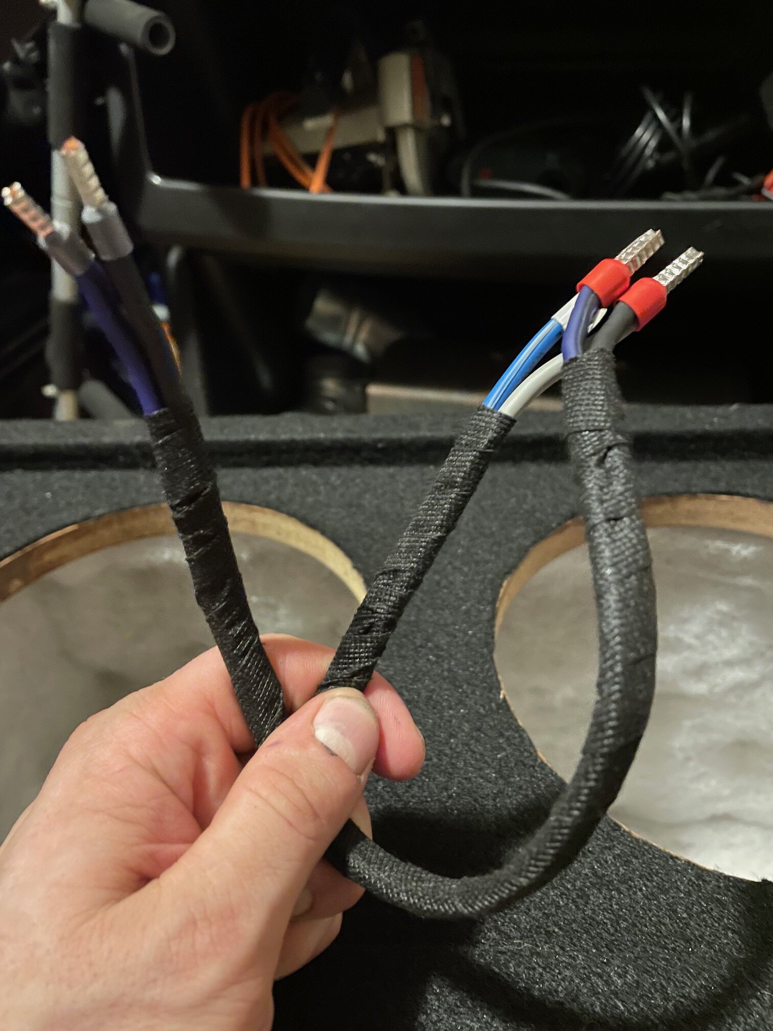
Next I put some ferrules on the wires because ferrules are awesome
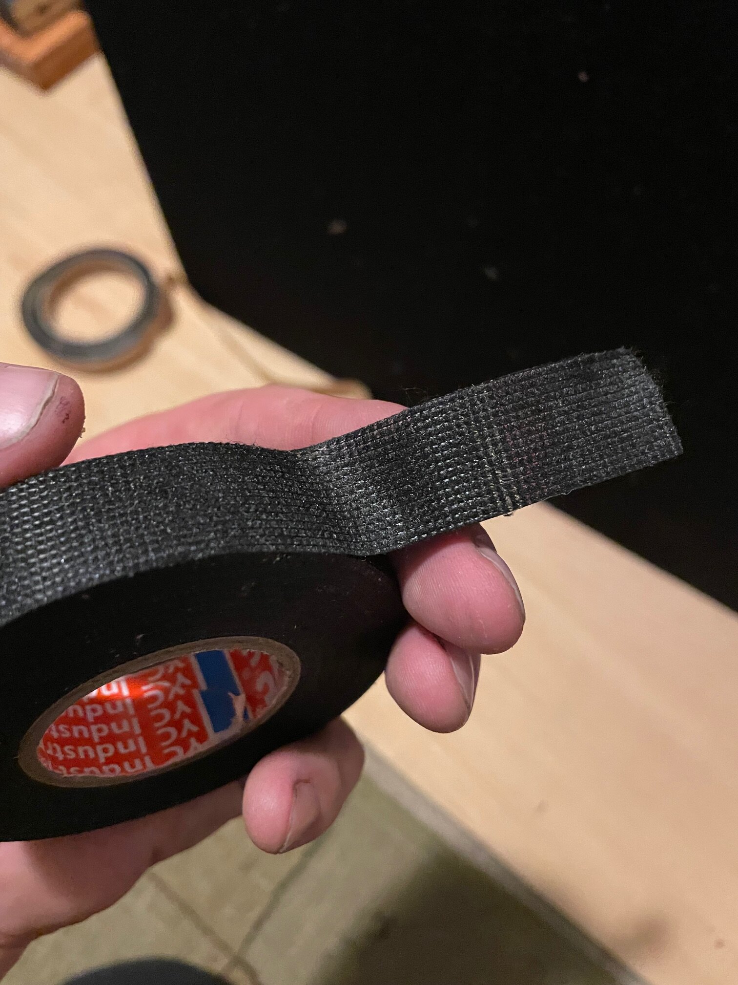
And Last I used a little Tessa tape (Fabric Tape) just to make sure the wires don't rattle against the box.
And that's pretty much where I have to stop, at least until I gut my other car, and start building an amp/battery Rack.
-
1
-
-
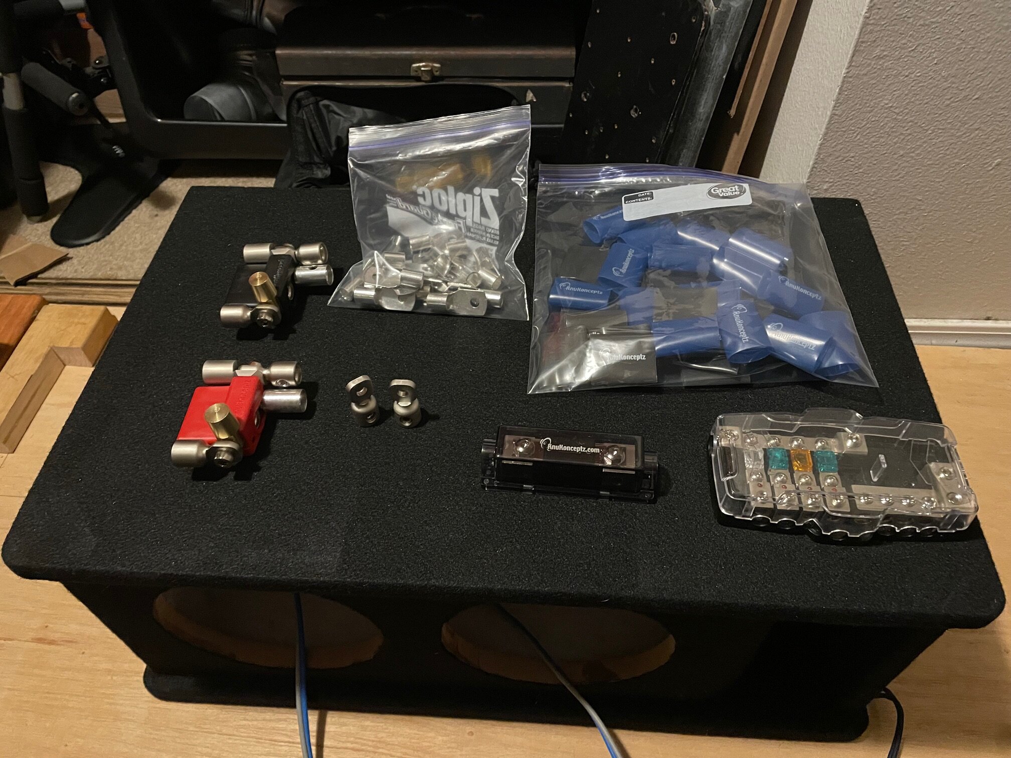
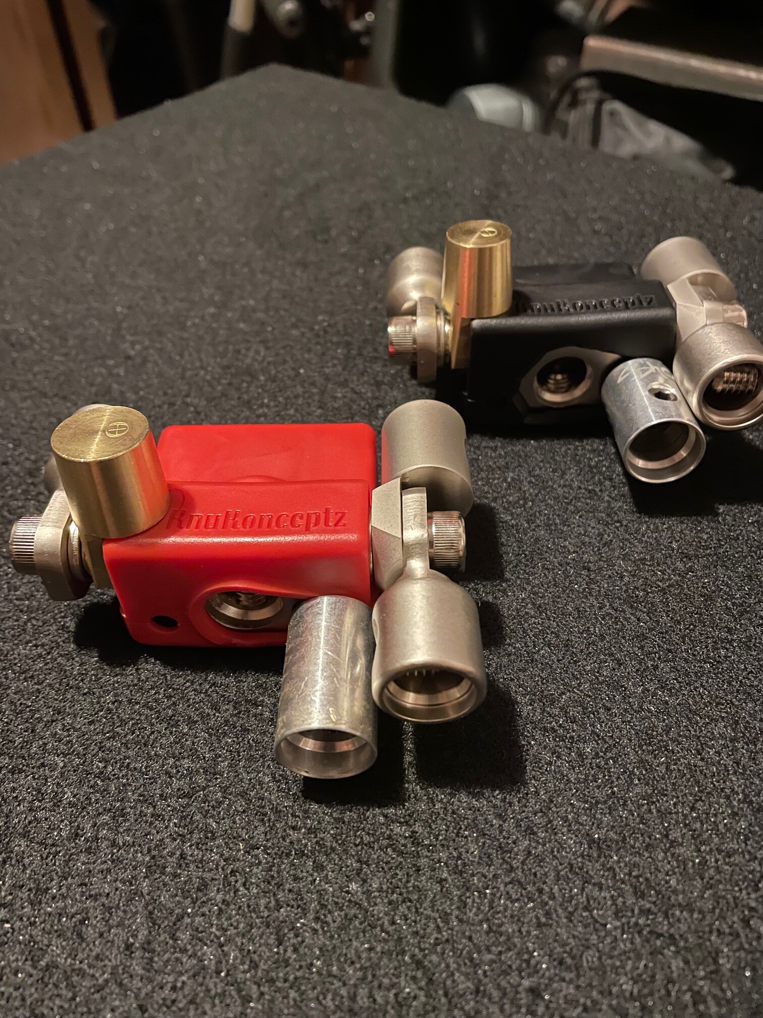
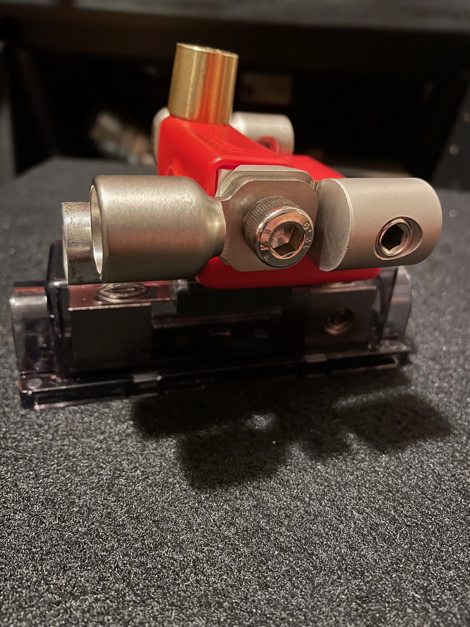
Next up is a bunch of hardware I ordered. I have a BUNCH of stuff I'm pulling out of my old car, but I figured I'd grab some goodies on black Friday.
Knuconcepts Ultimate Battery Terminals with top posts (Which I'll need to keep Mazda's computers happy
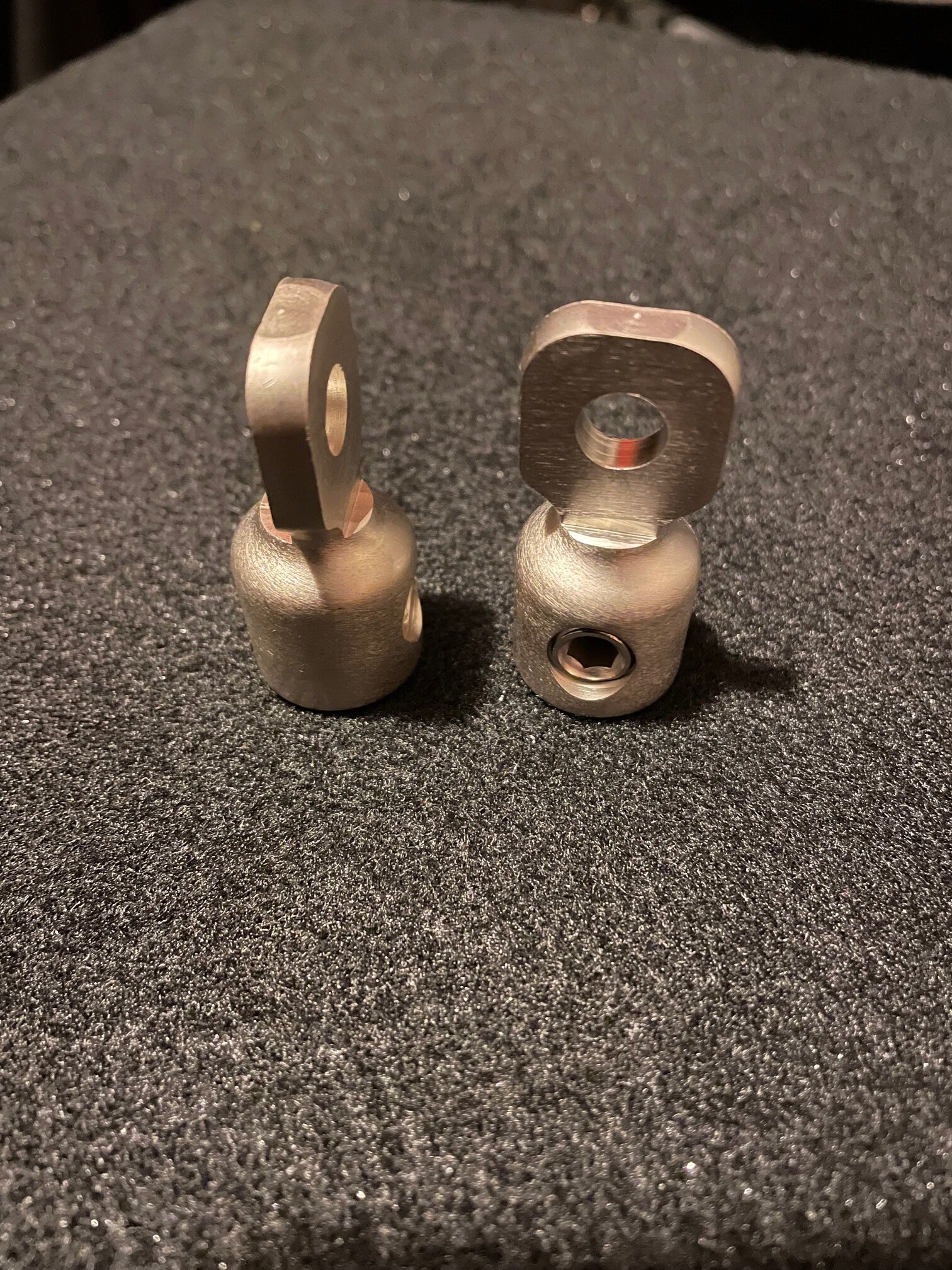
Picked up some of their 0/1 set screw adapters just because I like the look
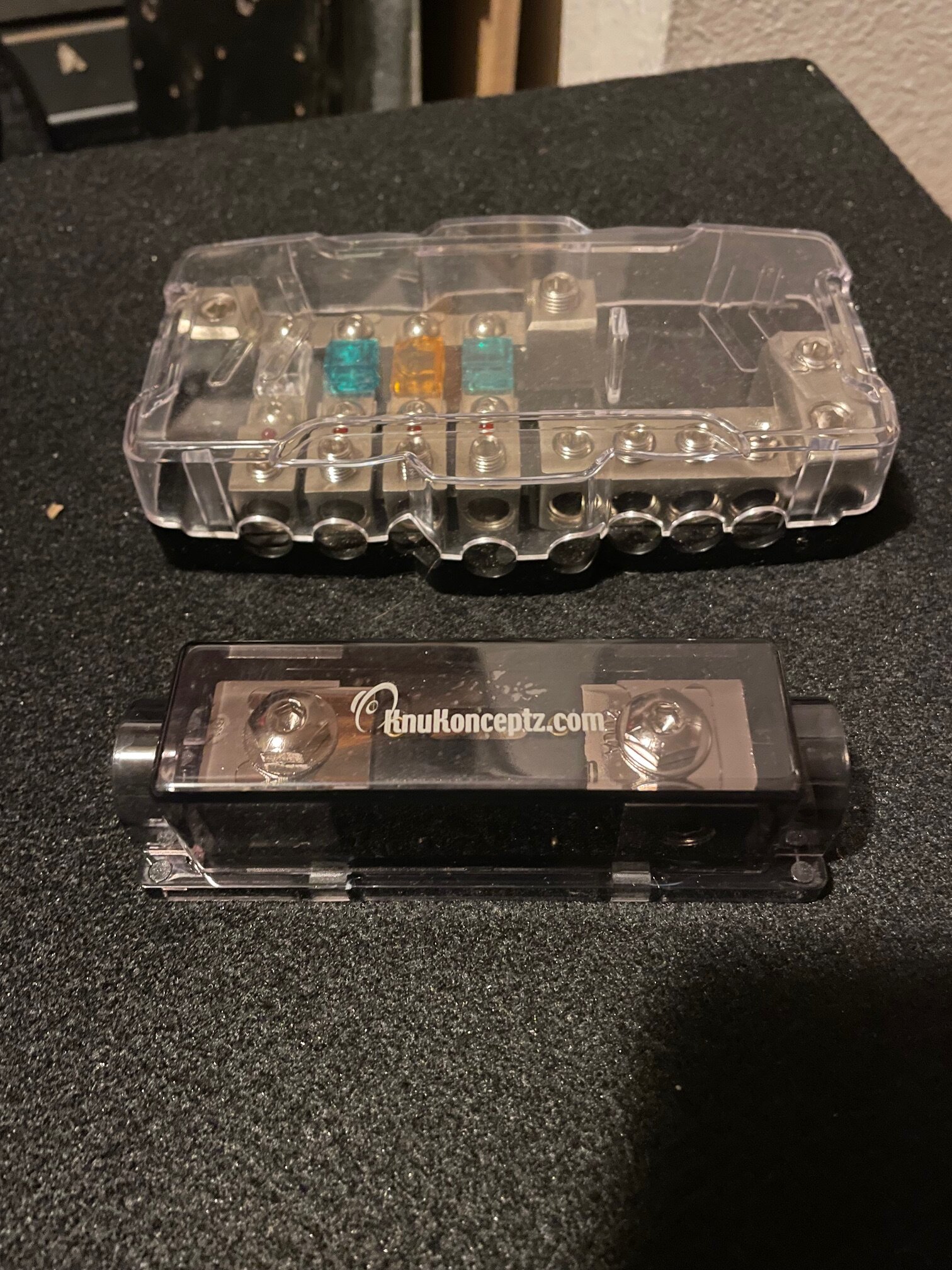
And last I have a couple fuse blocks. I have similar knuconcepts fuse blocks in my old build, so these are just additional. Not Sure I'm going to use the one on the top.
-
Hey Everyone,
You may recognize me from this thread here. Where I asked a bunch of questions and went through a ton of SketchUp designs, just to end up dropping a sub and buying a premade box.
Don't worry though, the premade box will not stay, it's simply a cheap way to test some parameters and help me figure out what box I want to build
So First - The Car Is a 2021 Mazda CX-5 which has some major drawbacks as far as power. Mazda uses one of those variable alternators that doesn't run all the time, varies from 12-25v, and as far as I can tell no reliable upgrade has been produced.
I did not realize this when I purchased the car, but I will not let that deter me from finding a workaround.
So what's the workaround? Lithium bank/Big 3 (probably 4 down the line)/XS Power D3400 if I can fit it under the hood.
Introducing the first piece of this build-
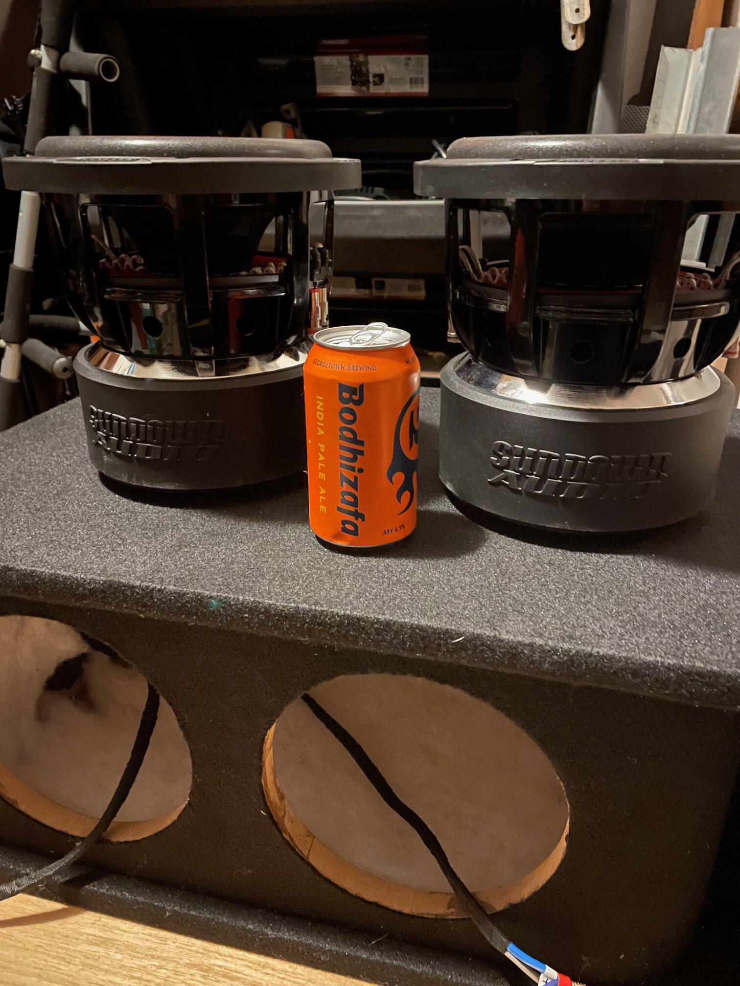
148AH 1200A LEV60F BATTERY LIFEPO4 - SLIM From Jag35 (Bodhizafa for scale)
The keen among you might have noticed the purple line drawn down the center of the battery pack, That is because I Intend to disassemble it and cut the pcb/busbars down the middle. Still waiting to hear from Jag35 if I can do that but according to some of their video's on other products this should be completely fine. If I can't I'll just skip the pcb and go busbars only.
I haven't decided whether I'm going to use 4 cells in a series or 2 x 4 cells in a series. I figure more is better, and I think I can fit both around my spare tire on their side if I notch a bracket near the spare tire.
I'll have to wait until I finish leveling that area and placing amps to see how much I can actually fit.
-
looks like I would need 2- 4" ports then. Thank you everyone for your input and help. I think my next post will be a new thread in the project log section. I'm still a long way from installing anything into the car, but I'll be doing the
Big- 3 (possibly 4)
hidden amp rack
Upgraded AGM up front
148ah lithium in the back
8ch Dsp, Active Crossovers
2-way in the front (3-way later with some custom a-pillars)
Full Sound Deadening Treatment
And an SQL Tune using a Dayton Audio Umm-6
Most of the gear I have installed in my 2006 Scion TC. I still need to rip out all of my gear and get that car sold before I start working too much on this one.
-
Another Idea I had involving Aero ports
I honestly have no Idea how to calculate aero ports, so I copied this box from ebay and modified it into a wedge.
The only Issue I have it that the ports are too close to the bottom of the box.
I'm thinking about either throwing some 45deg adapters in or running the ports out the right side
The other issue is that I am trusting an ebay seller, hoping that dual 3" ports @ 13" each tunes the box to 32hz.
Enclosure Details:
- 3/4" MDF Cnstruction
- Black carpet (charcoal or light grey carpet may be substituted upon request)
- Port Tubes - 3" flared x 13"
- Tuned to 32 Hz. (frequency is adjustable upon request)
- Exterior Dimensions - 26" (wide) x 14" (tall) x 16.75" (deep)
- 2.0 Cubic ft - Net Volume
------------------------------------------------------------------------------------------------------------------
-----------------------------------------------------------------------------------------------------
-
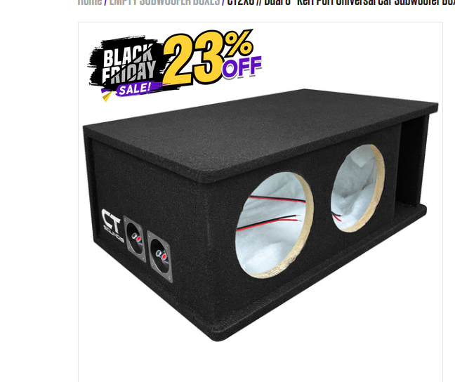
Well I bought one of these...
(It's the one I modeled @ 39hz in the last post)
I know it's a prefab but it's on sale because of black friday so I figured I'd try it out.
I bought a bunch of other stuff too, and i'll post it all when it gets here.
-------
-
Hey Guys, I appreciate everyone sending me Subbox pro Designs using the specs from the website. That's essentially where I started and the Box was taking up too much space in my rig.
By adding a wedged back to for to the seats, I gain 2-3inches of trunk space, and add .13cuft (the displacement of one driver) back to the box.
So I've made a few compromises!
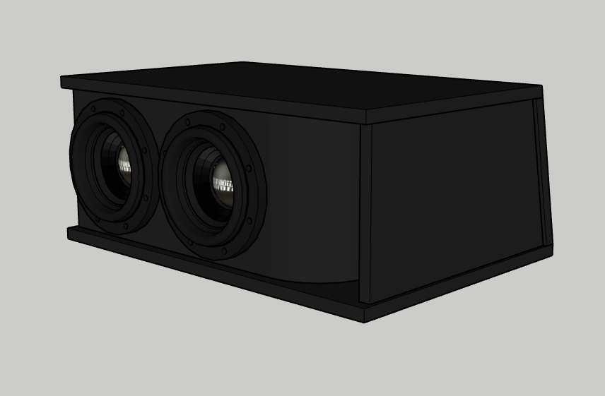
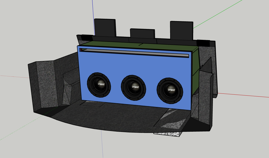
I'm only going with 2 subs. My buddy wants the third for his truck, and a 2ohm load of 2000w is a more Ideal match for my amp. So here are my newest renders.
At the Bottom is a 32hz option with all factors the same excepts size and a couple disclaimers. Any Pro's and cons of 39hz vs 32hz would be appreciated.
1.88CuFt Gross (1.62cu Net ) or .81cuFt per sub
3/4in MDF With Kerfed Port
Tuning - 39Hz
Port Length - 28.02"
Port Area - 24sqIn
Port Width - 2.52"
Kerf Fold Length - 4"
Kerf Fold Width - 2.50"
--------------------------------------------------------------------------------------------------------------------
--------------------------------------------------------------------------------------------------------------------
Thinking I will round the hard edge of the port on the right as well as the opposite corner, since kerfing on an angle is impossible, at least I think it is.
--------------------------------------------------------------------------------------------------------------------
And this last image shows a 32hz Option but it's 1 3/4" wider, 2" deeper, and gets in the way of that 3rd seat folding down. I know that seems like a small change but it makes the difference of me being able to drive my brother, bassplayer, and their ampscabs to shows without taking out the sub box (I'm in a band) or taking two cars.
One More Pic just for fun. This is the Boneyard of failed box designs lol!
-
I had a feeling that would be the case lol. Well I’m glad I’m knocking out all the wrong ways to build the box lol. I think I can modify the port to make it wider. Also, I’ve seen boxes where each sun has its own individual section which would essentially “widen” the port by a factor of three, with each sub having its own port/chamber. It would also help structurally with bracing. Maybe I’ll try that next
-
Haha! I checked the website and ran back here to tell everyone but you beat me to it! Thanks a million. I'm still not sure how I'm going to use these subs but I am sure it will be awesome!
Just Saw you're in WA. I live downtown Olympia, and work in Seattle. Check this thread out and lemme kinow what you think
I'm trying to put too many subs in too small of a space with not enough power : )
-
I would help you for free but I'm all the way in washington state
Try greasing the wire, cutting a large grommet passthrough, and pulling it through the firewall. the hardest [art is getting it started, but once it's through it should be a breeze.
-
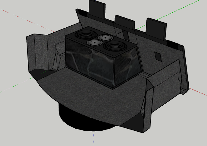
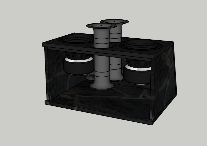
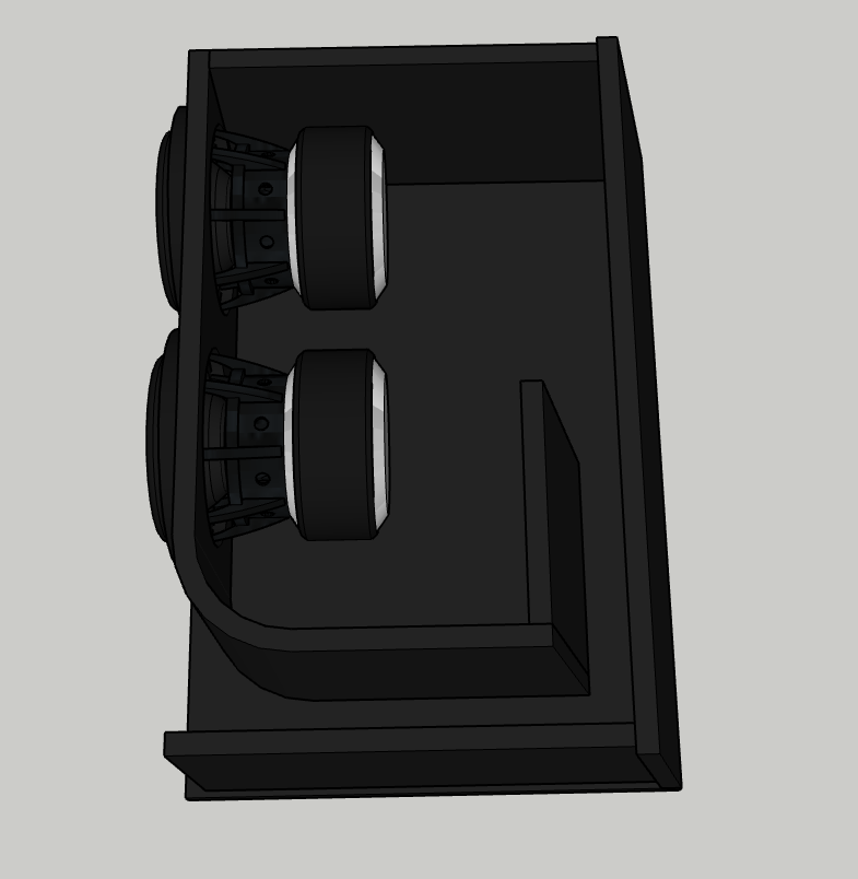
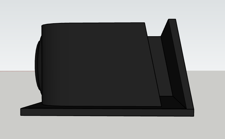
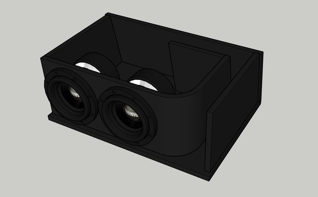
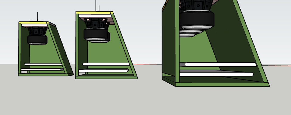
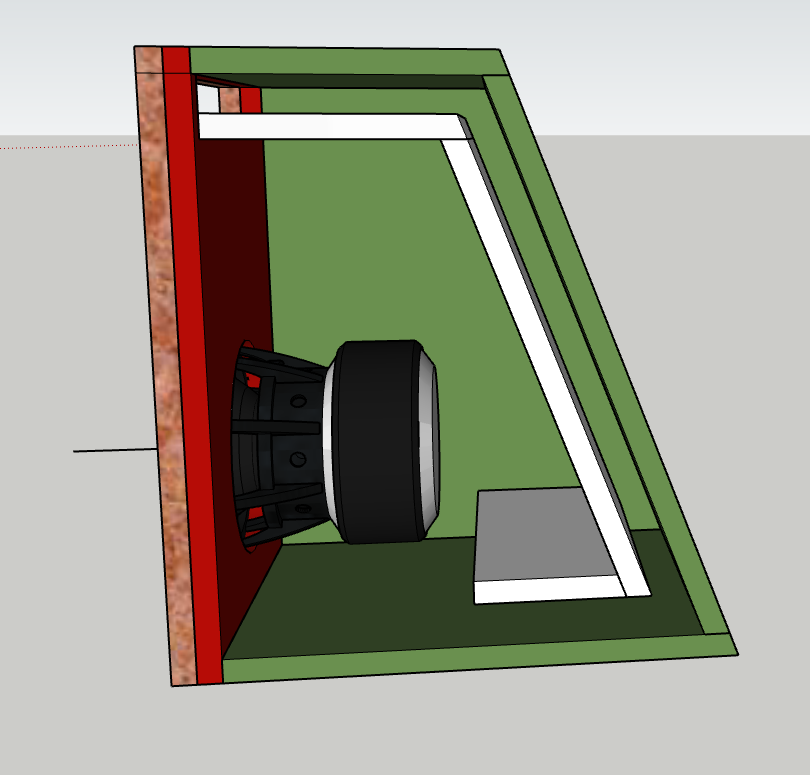
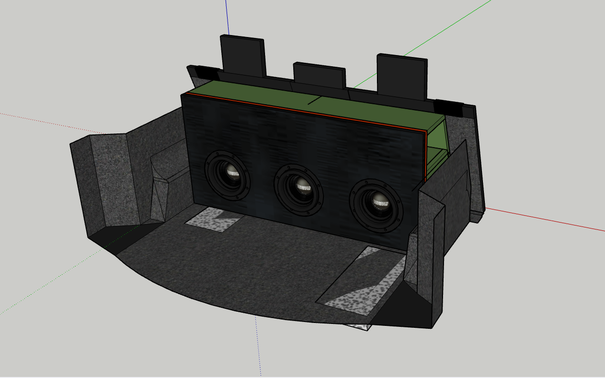
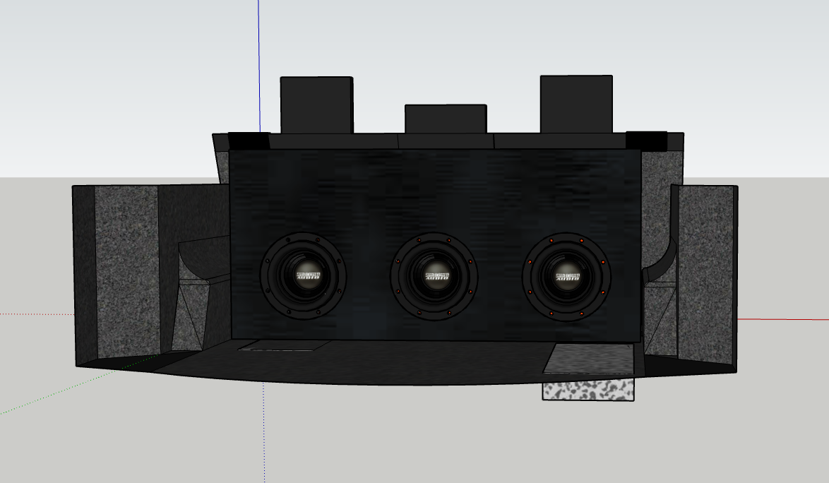
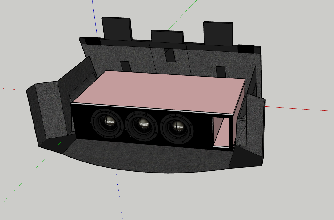
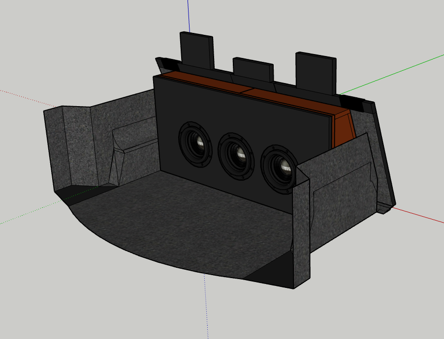
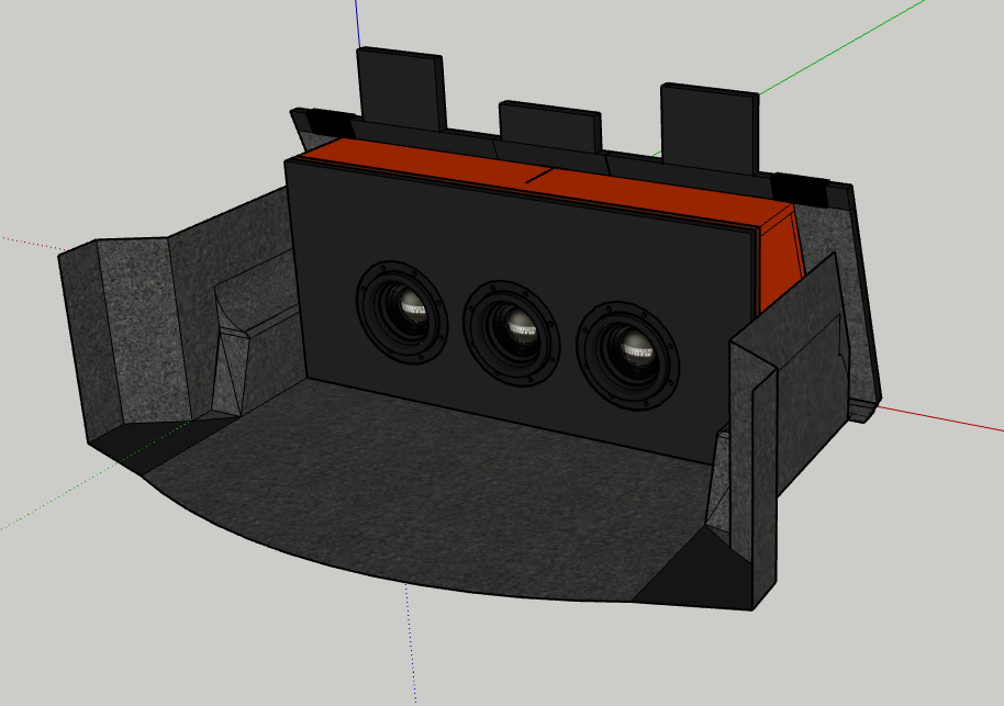
Decided to do some top mounts and I think I might have my answer. These boxes are using 14sq in of port per woofer, 1cu ft of box space, and 32hz tuning.
But I think I have my design. Top mount to protect the subs, might even invert them to show off the motors. Any feedback is appreciated, please tell me what I'm forgetting. 
-
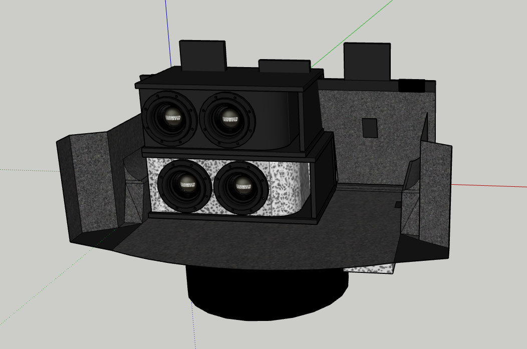
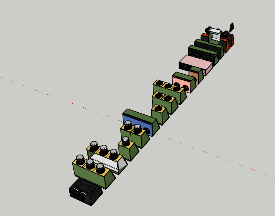
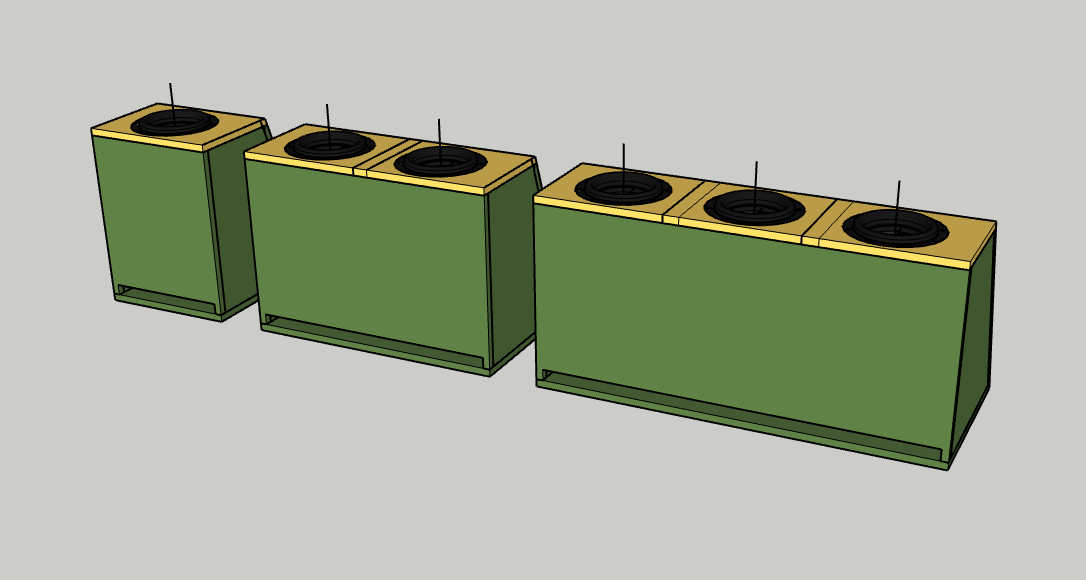
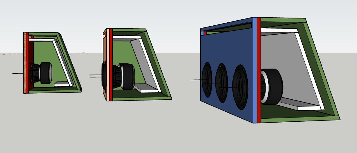
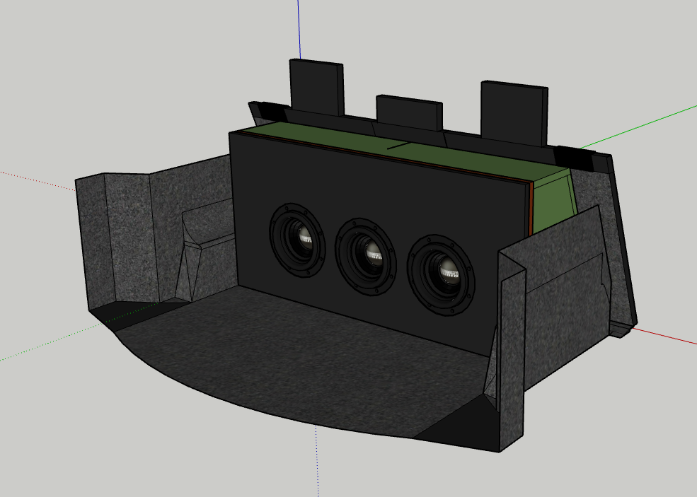
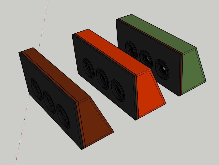
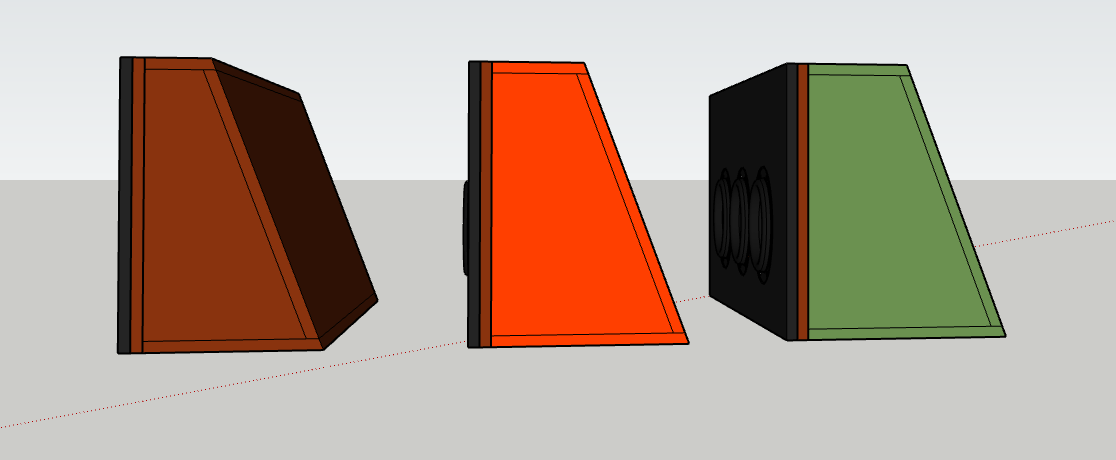
Decided to go modular this time. Sticking with wedge.
Port area is 14/28/42 to 32hz
and box area is 1cu/2cu/3cu
Here's a couple designs. No bracing because I didn't want to design it, but I would probably do something similar to my previous posts.
-
Hmmm, Back to the drawing board then. I know the amp is slightly underrated for these subs, but I’ll probably never have them at full volume anyways, would it be better to run two then? I was thinking the extra cone area having 3 subs at ~800w a piece would be better than 2 subs at 1000-1200w a piece.
also Williston dyno’d this amp at 2700w at 1ohm which would put it at about 900w per sub.
not sure how close I’d get to that in a real world scenario but is that extra 100w per sub that big of a deal?
I think the 2ohm dyno was ~2300w
-
So after a little modeling, Here are the specs.
32Hz Tuning.
2.75 CuFt NET (after Displacement, Port, and Bracing)
41.42 SqIn of Port Area
3/4" Material (Still Deciding between Birch and MDF)
Double Baffle
Braced (Looking for feedback here)
Main Issue I'm worried about - I have 3 1/4" between the port and the right wall of the car. Is this something to be concerned about?
-
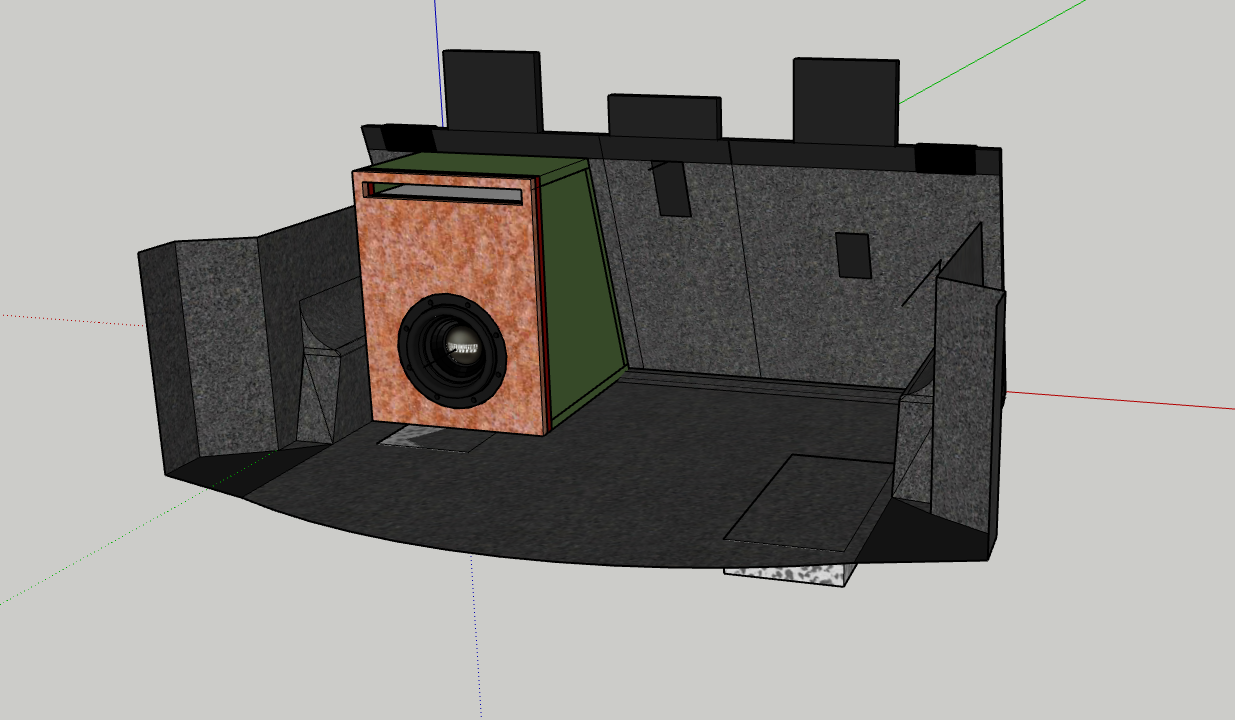
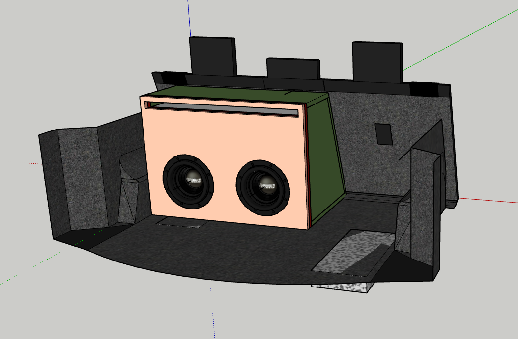
Thank You Everyone for the feedback!
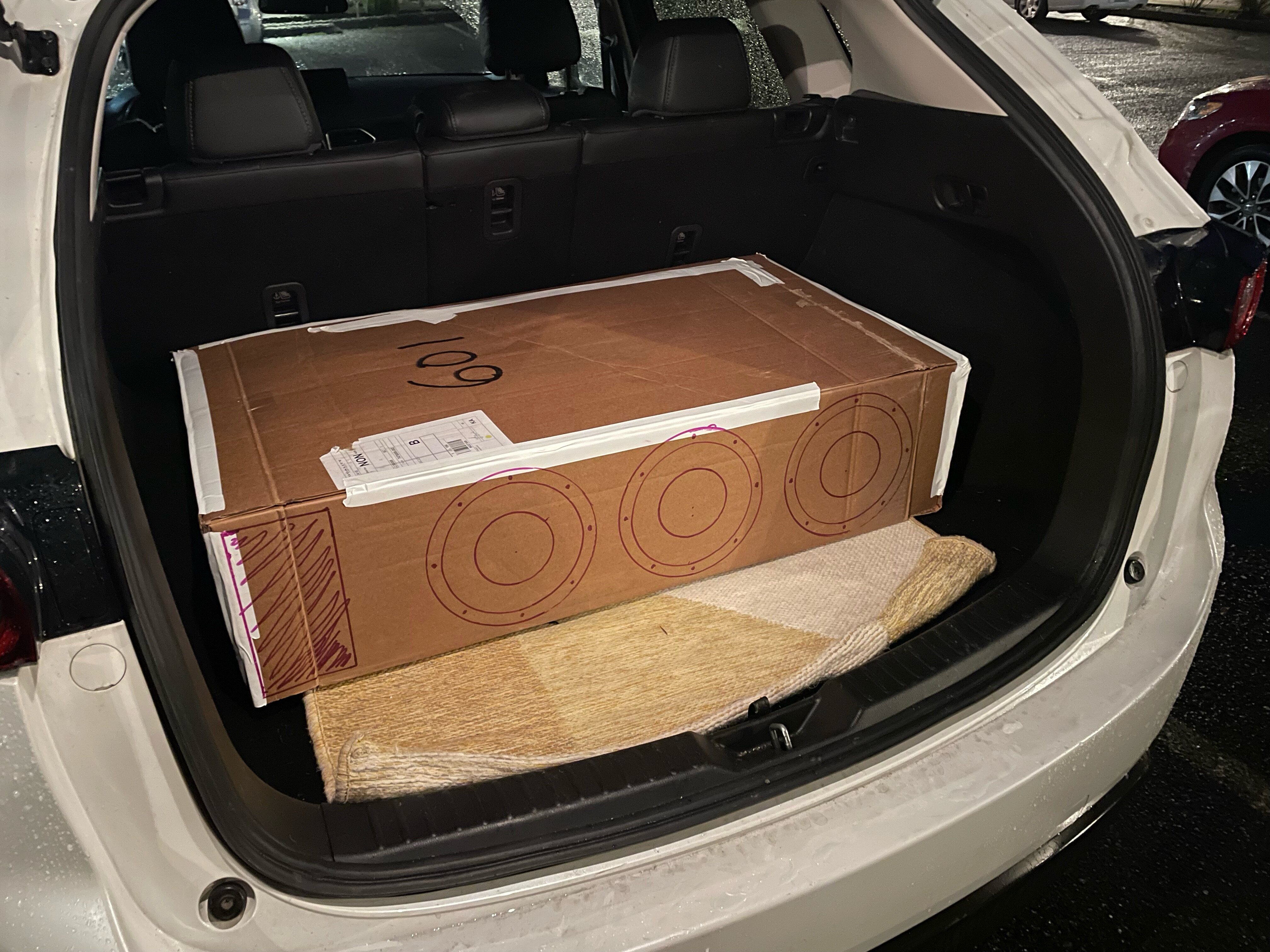
First, here's a couple of pictures of some cardboard boxes to test RealWorld size.
This one wasn't going to work. Too deep and took up too much of my trunk.
The wedge on the other hand...
This allows me to still use my trunk. This is the biggest of the wedge boxes I previously modeled. Coming in at 3.94 CuFT before displacement or port. See next post for some math.
-
51 minutes ago, mel80 said:
bassed on v3 specs im going to guess ur going to want 3cft net and about 46sqinch of port , though u have room to play with port area , less sqinch of port = less port lenght so u can use that to play with ur box design to get it to fit int he car nicely , i would stay within the 36-50sqinch's of port though andthing smaller then 36sqinch is likley to have port noise
Ok cool, I’ll mess around a little bit with the design. If I can get the box slightly shorter to line up with the wheel wells I might do that.
-
Decided to make one more "conventional" box before I call it a night.
41" L x 10" H x 22.85" D
NET 3 cu ft
36 sq in of port
tuned to 32Hz
port inlet 4.23" x 8.50 " x 24.22 Inches Long
This box just feel like it takes up so much more of my trunk, although I haven't accounted for port area on the other models
-
16 minutes ago, Joe X said:
Without sub specs you should call sundown and get the optimal box specs and go from there.
My only comment is that you might have space for 2 12s in that vehicle which would be far louder, also 3 subs lead to impedance mismatch for most amps, you will need a constant power amp to get the most power form a non standard final impedance, some examples are the Taramps smart series and the rockford fosgate CP series.
the SIA 2500.1d is Sundowns version of the same tech that Taramps is using. Wiliston Audio has a video up on it. Also I'm prety sure no amp ever see's exactly one or exactly 2 ohms. When you account for box rise and other variable the resistance is constantly fluctuating. So I see no reason why 1.3ohms would be bad for an amp thats rated down to 1ohm.
Also I realize I probably should have gotten different subs but these are the ones I got so I'm gonna use em!
-
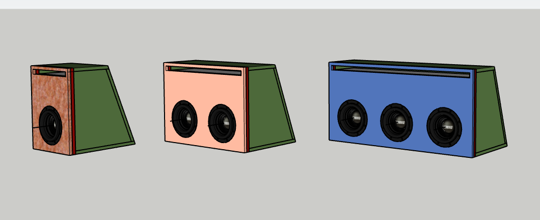
Did Some work on sketch-up and did a little math.
Came up with three wedges, All measure 19" (H) X 41" (W)
3/4 " Plywood and double baffle but no ports yet
The Smallest -
12.75" deep / 2.74cubes (2.35 with displacement)
Obviously I haven't factored in bracing or port either. Hoping to find out how much i need and adjust the design
Medium:
14.75" deep / 3.52 cubes (3.13 with displacement)
getting closer i think
Large:
15.75" deep / 3.97cu (3.58 after displacement)
what are your guy's thoughts?
-
good to know, i'll look into it!


Eco's 2021 Mazda CX-5 Build - UPDATE - 3/08/2024 Ruining my backup set of A-Pillars!
in Member Rides & Builds -- Show off your whip, Show off your System!
Posted
------UPDATE-------- 3/8/24
May have trashed $80 worth of A - Pillars..... We'll see.
So I ordered some spare A-Pillars so I could keep the stock set and swap them back out when I sell the car.
The Drivers side is from a CX-5 with Bose (Which I don't have) and the passengers side is from a cx-5 without tweeters in the a-pillar (which I do have) No worries though, the plan is to cut em up, fiberglass/fill, and re-upholster them with OEM headliner material.
Here we go!
Extra A - Pillars.
I highly recommend getting a second set before you start. You never know when you might want to go back.
The plan is to mount the 3.5" Midrange and the 1" tweeter in the A-Pillars without losing the vents or the side airbags (not pictured)
Drilled out these plastic tabs that hold the vents. Some short screws should make nice replacements when I fasten these back on.
And Just like that, it's free.
Always check the backside first for mounting clips. We want to keep all of these if possible.
Made an ugly rough sketch. Erring on the small side (you'll see why later)
Pre-drilled some holes to make life easier.
Rough- cuts at first.
Then more rough cuts.
Quick check to see fitment.
Had to throw them in the car though to really get a good Idea.
And the other side
And both sides
And this is where I decided to destroy the Pillars.
Not sure if you can tell from the last picture but the pods are WAY too high. I got focused trying to go around one of the mounting clips and forgot to check these before I went to far.
Sooooooo.... I decided to move them down as far as they could go, which is what I should have done the first time.
So now there's a huge hole I have to fill or I need to get another set of A-Pillars.......arghh
Here's one installed at the new height. It's much better but I'm bummed about trying to make this panel look factory again.
So that's where I'm at for now. Gonna call some junkyards and see if I cant find some A-pillars nearby. They'll be like $10 if I can find em that way.
What do you guys think? High or low?
And another question, the tweeters are aim able but the midrange is not. These speakers are supposed to be pretty wide when crossed over correctly, How important do you think it is for me to aim the 3.5" midranges? I'd prefer to put them tucked into the corners as possible (like it sits now) or I could get a lazer and aim these puppies in-between The driver and the passenger.
Another question, I'm going to add a center channel speaker to take advantage of my 10ch Helix, in anticipation of this, would it effect the way I aim FL anf FR?