

PandorasCustoms
-
Posts
144 -
Joined
-
Last visited
Content Type
Profiles
Forums
Events
Media Demo
Store
Collections
Videos
Posts posted by PandorasCustoms
-
-
I agree that the stain look is pretty slick.
And, you don't see ports like those much, good work.
What is the volume after displacement?
And that is a CVX, right? How do you like its performance? I have always been interested in the performance differences between the CVX and the L7, but haven't been able to get around anyone with them in to get a good listen.
-
As Anubis said, the minimum distance from the rear of the enclosure to your port entrance should be the width of the port. This way, there is no airflow reduction going into the port.How much space should I leave behind the port?
The port width and depth (height is automatically assumed since this is a slot style port), change the tuning frequency. So, depending on what you want your frequency to be is how big the port needs to be. Basically, make it as big as your design allows, as this will continue to decrease Air Speed at the Port. But, also remember, that as you continue to increase the port size, the net volume of the enclosure continues to decrease. So, you have to juggle between how much volume you want and what air speed you want.The space behind the port is 4". That's where I'm the most confused. Don't know how wide/deep the port should be. -
Yeah, that is a very unique connector. Never seen one quite like that, but I am sure some manufacturer's do it for reasons such as this.
And, the box looks good. Any plans on covering it?
-
Actually, come to think of it. I was working on a system for a friend of mine in his VW Passat, and underneath of the dash next to the inside fuse box, there was a spare terminal post that was rated for 60 Amps. It was weirdest thing I had seen, but since the battery was practically impossible to get to (it was underneath of a plastic cover in the center of the engine compartment near the firewall), and it was only a small 350 watt system. We went and hooked the primary wire up to it, and it worked perfectly. Tested all voltages, and everything was working with no change in the electrical systems of the vehicle. Of course, if the system were anymore than 500 watts, I certainly would have spent the extra time to get directly to the battery.
-
Also, this red "box" you are talking about, it is inline between the alternator and the battery?
I know on my Uncle's old F-350 the starter solenoid actually ran between the Alt & Bat.
And, if you are running your amplifier from a solenoid post, it probably won't hurt the amp, but may ruin the solenoid.
Got a picture? I am sure someone could tell you what it was if you had an image of decent clarity.
-
My explorer does about the same as that. Just under 15v (between 14.6 ~ 14.9) at idle.
And, it has been like that for over two years.
So, as long as it isn't bouncing around, you shouldn't have to worry about it.
-
With depth and width of the enclosure, unloading won't really be a problem unless your port is pretty large. Right now, I am guess that your port is 3" ~ 4" wide? So, woofer placement is going to be aesthetic for you, you might want to position it a certain way if you are going to be adding on an amp rack as well. Or something along those lines.I'm just gonna bite the bullet and resin it all, and then resin in some 45's too. So the woofer would not load if it was mounted in front of the rear port wall because of how close it is compared the rear wall of the box?Unloading generally only happens when the back-pressure for the woofer is low due to not enough air being behind it on heavy notes. This is why subsonic filters are required to be set past port tuning because the woofer loses back-pressure below port tuning. This is also why you don't hear about this in sealed enclosures, b/c the pressure is constantly sealed inside and can not escape.
-
Technically the first option would be better.
But, it is just extra displacement that will have little benefit.
And, just for technicalities... It is 45'n the corners. 90 is the standard right angle.
-
Welcome to the CarAudio world whosAmp.
I think I got started when I was 13 working on my sister's boyfriend's 92 Ford Ranger.
3 Original Solobaric 12's in a ported enclosure with the old school ZR1000.
But, that was then, this is now...
As far as this design you are looking at.
A center port is fairly easy to build, but you have to be careful with the depth of the enclosure.
If you want calculate out the depth of the port to be less than the depth of the enclosure it is actually really easy to design (And looks a little more custom too).
A slot port like Anubis posted is one of the most common, and actually one of the easiest of ports to design.
And, as for "what type of port"? That is actually personal preference. Every type of port will perform the same as long as they are designed properly. The port style has no effect on the audible output of the enclosure. What does have effect is Port Area & Port Volume.See and that's the thing, i don't anything about how to build these ports or which is better for the type of enclosure I'm building.How big of an enclosure are you looking at building? Basically, how much of the trunk do you want to save?
-
I'm the kind of person that wants to know "why?", not just get the answer. You don't learn anything that way, so if I can get not only the answer but a brief explanation why that is then I not only get my answer but a better understanding of why.
Definitely an admirable trait.
Doing the 45s on all the corners will reduce resistance. Resistance is the killer for a ported enclosure. Resistance will bring reduced airflow and increases port noise. This will reduce your SPL ratings and could possibly create some very unwanted "puff" noise (Air rushing out and causing to much friction) around the port tuning. I had it with my first ported enclosure because I myself did not do any 45 corners.Is 45'ing the corners going to be something that's going to give me a noticeable gain in output on this setup? If I won't hear a difference then I don't want to waste my time and/or money doing that.This is also why Round ports are preferred over Square & Slot, as they have no rough edges and have less resistance.
-
Wow, probably the easiest box design and people making it complicated lol
It isn't the box design that is being made complicated, it just a question as to which is better and why?
Personally, I feel like if you aren't 100% as to why, then ask or try. It is the only way to guarantee your hypothesis or idea.
-
No, it's for a DD 2512....but my question was more of a general one, I never knew if one way was better than the other or why
Hey, that reminds me, I have BBP6 on my HD somewhere. I tried using it a while back, couldn't get it to work out like I thought it should so I stopped using it...seemed too advanced for me. I'm gonna have to check it out and keep messing with it.thats a good way to start. i try using bass box pro still havent figured it out completely. the more u do it the more ull see different ways.
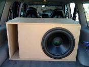
So check out this box, this is why I asked the question...I always see boxes done like this instead of close to the port as suggested

More or less people do that for appearance. Ive never heard a difference. Is this box for SA's?
I think that you are going to find minimal noticeable differences with the positioning.
What was the width of the Sketchup design? B/c the shorter the width the less of an effect you will see.
-
ok this is a drawing i made on paint explaining what im trying to get at...
i need to know if the one on the left would work or not... if not just tell me and ill leave the pioneer out of my car
The only thing you need to remember about this design is that the power handling will be uneven between the woofers.
The first channel with two will split the power rating for that channel between the them and the second channel will provide full power for its channel.
So, if all three woofers are 200 watt RMS and the and the amplifier is 800x2 at 4 Ohms, then this idea would not work, as the "pioneer" woofer would end up receiving double its recommended RMS rating.
In personal experience, you get better sound from two woofers being pushed closed to RMS than you do with three woofers under-powered.
-
I would assume that placing the woofer closer to the port will force more air out of the inside end of the port and limit the possibility of unloading
-
I was going to steal that image, but decided to write it out instead.
-
Woofer wiring is easy to remember as long as you think it through.
If you wire them in parallel (Amp to Woofer "A" Positive to Woofer "B" Positive & Amp to Woofer "A" Negative to Woofer "B" Negative) you always half your impedance.
If you wire them in series (Amp to Woofer "A" Positive, Woofer "A" Negative to Woofer "B" Positive, Woofer "B" Negative to Amp Negative), you always double your impedance.
So the more positives you link, the lower the impedance goes.
-
In this design, the woofer location has minimal effect on sound (As long as your are placing it on the same wall as the port).
But, what is the depth of the woofer, and the depth of the enclosure? There is a general idea that you need to leave a few inches between the woofer and the back section of the enclosure for optimum performance
BTW, Nice Sketchup...
-
I have been floating around on the forums for a while, and finally decided to make a post on what I feel is an important topic.
Check Please!
This looks like it would make an invaluable addition to my already limited set of tools for installations and tuning.


Simple box question.. so easy
in Subwoofers / Enclosures
Posted
Well, if you are using the design shown above, the following needs to change...
Port Height: 13.5" -- The port height is going to be the same as the box height, minus the 1.5" for the MDF.
Port Width: 3"~4" -- I would try to stick to a 3"~4" minimum width just to allow enough airflow.
Port Depth: ??? -- Modify the port depth to work in your favor, and achieve your desired tuning frequency.