
1point21gigawatts
-
Posts
3740 -
Joined
-
Last visited
-
Days Won
93
Content Type
Profiles
Forums
Events
Media Demo
Store
Collections
Videos
Posts posted by 1point21gigawatts
-
-
I don’t even know why I asked that stupid question about what’s more important to you. I’m getting tired. Lol! I’m about to go to bed. Think about what type of enclosure you want me to draw up for you. Do some research on both and comparisons and then we can touch base tomorrow.
-
4 minutes ago, akuma4u said:
thats a good question. im kinda torn between the two. however im leaning towards LOUD. I love the feeling of my face and body being impacted by the bass.. the physical sensations.
In this application since it isn’t a wall or something like that, an aero port would be louder and sound better. The ported enclosure I designed for myself was strictly spl because it was designed with a lot of port area and bandwidth wasn’t something I cared about when designing it. I could use a lot of port area in that build because the enclosure only being about 4.6 cubes after displacements on around 6000-8000 rms after rise. But I decided to change to an aero port because in most regular applications an aero port is better and louder because air flows better through a tube than a rectangle or square and the response is better because of that too. But on that spl slot ported enclosure I designed would probably be louder than the aero ported one I designed but not sound nearly as good. But when it comes to your build, an aero port is the best way to go, no doubt.
-
4 minutes ago, akuma4u said:
awesome, thanks <img src=">
You are welcome. Question though, have you considered an aero ported enclosure? I was wanting to do a slot ported strictly spl enclosure on my application but, I decided to do a musical aero ported enclosure instead because it would have spl and be musical, have a wider bandwidth, more efficient, a better air flow and easier to design and build. Even though I could design and build a complicated and difficult enclosure, easier is always better.
-
5 minutes ago, akuma4u said:
praise the lord.
i shall get this made.
all i need now... is a cut sheet/blueprint so i can pass it to my builder. can you assist me with that?
Yes.
-
4 minutes ago, akuma4u said:
im not looking to blame anyone. help is appreciated no matter what.
what i find is that people just have different opinions on enclosures and what works. port area is a big area where there are opposing opinions.
yes, i can build several boxes and test and this is what i will probably end up doing. will be costly but i guess i have no choice.
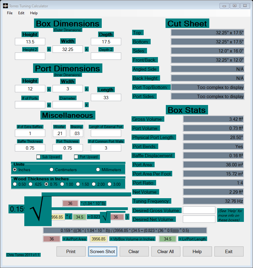
as for now,. i am trying to build the box 1point21gigawatts told me to , but since i am limited in space, the closest i could come up with is the following. mind you my max dimensions are 13.5 tall x 32 wide x 17 deep , i had to push it .25 in the width and .5 in the depth to get more airspace.. i will have to router the outer edges to slide this thing in .. it will be TIGHT.
maybe 1point21 can take a look and tell me what he thinks.. this is the BEST i can do with the space i have...

That would work. Since I factored in the impedance rise best case scenario instead of doing port velocity calculations on 2000 rms. That enclosure would work just fine. It would have good bandwidth and good output. I like it.
-
Read this. People believe things when they hear it from reputable sources.
https://ddaudio.com/subwoofer-enclosure-design-bending-the-rules-maximize-output/
-
When you gather information from all over the place and don’t use that information correctly to weigh right from wrong then it’s easy to become confused and indecisive about a matter. I skimmed through them screenshots and seen facts and fiction and didn’t even have to study it and keep reading it to asses the general knowledge from it. If I were a noob that didn’t know how to build enclosures, I could use that information you posted and come to a conclusion quick because I’m smart. If you do the mathematics on the port area of both enclosures I told you to choose from, one has 12.3 square inches of port area per cubic foot and the other has 16 square inches of port area per cubic foot. That’s kinda what was told to you in the screenshots you posted. And 2.3 cubes is 15% bigger than 2 cubes that’s recommended. That’s not enough of an increase to cause the subwoofer to reach its mechanical limits and bottom out and damage the subwoofer. That’s 5-10% less than the maximum increase before bottoming out would occur and the amp would have to be stronger to cause that on that subwoofer. You have understand each subwoofer is different and designing an enclosure has to be done by factoring in the t/s parameters. The recommendations of sizing is just a basic idea. And when it comes to port noise, the more the rms and lower the tuning, the wider the port has to be to not have port noise. More rms increase port velocity and lower tuning increases port velocity. Some designers and builders use less port area to accommodate for the area available when building an enclosure with a lot of subwoofers and it helps with bandwidth and accuracy depending on the application and design, but takes away from the output. As long as it isn’t a crazy amount of port area, the bandwidth would be fine and it wouldn’t reach mechanical limits. That why I suggested an spl slot port enclosure with 16 sq” per cube and a musical aero port enclosure with a little less than 12.3 sq” per cube. And a 15% increase would increase output without reaching mechanical limits. Most pros that compete increase the sizing of their enclosures by 10-20% to increase output and they throw more than rated rms at the subwoofers. Plus recommendations about sizing is just to reference. You have to factor in the t/s parameters of the subwoofer and the rms of the amp. That amp 2400.1 you are using isn’t doing 2000 rms after rise. Rise differs on each frequency, subwoofer and application and cabin area surrounding said enclosure. Dude just messaged me earlier today and he is rising from 1 ohm to about 4 or 5 ohms and on a bass 30k only doing 9000 rms. So a 30,000 rms amp is only doing 9,000 rms after rise on his set up on whatever frequency he tested it on with an amm-1. So with that said, the enclosure has to be bigger because you are probably doing around 1000 rms. That figure is based off of the specs of that amp and the absolute lowest rise if the subwoofer, application and cabin area surrounding it permits minimal rise from about 1 ohm to 2.5 ohms. Rising from 1 ohm to 2.5 ohms is minimal rise and would make any bass head happy as shit. Before I begin to type or draw something up, I learn every piece of the equation and factor in so many different variables and calculations and base the variables off of facts and if facts are unavailable and it’s something like impedance rise, I would factor in the best possible scenario when it comes to that when designing an enclosure because if I calculated using the worse case scenario of impedance rise then it would leave too much room for error. Factoring the best case senecio leave no room for error when it comes to that variable. Then on some variables I have to factor it worse case scenario to ensure no errors arise. Averaging is something that works with some things but averaging can be problematic if something in the equation is below average or below average.
-
 1
1
-
-
Around 2.3 cubes with about 37 sq” of port area tuned to 32hz. 4” wide port that yields a velocity slightly under 17 m/s. I had already told you this. Trust me dude. It’ll sound so good and loud. Or if you want more efficiency, then just incorporate a 6” flared aero port instead on the same 2.3 cubes net volume. The port area is about 9” less but the efficiency would make up for it. Less port area is needed when using aero ports. Think of it like this. What is used for optimal flow? What shape is a straw or pipe?
-
1
-
-
-
Maybe something malfunctioned in your cc-1 recently. Idk. Weird.
-
You are using the cc-1 incorrectly then. It does the same thing as the dmm method but it is better and can do a little more. The sfb amps are full bridge amps that make it where you can set the crossovers with a dmm. But regular half bridge amps subsonic filter, even though a subsonic filter and high pass filter are basically the same thing, it won’t allow you to set the subsonic filter using a dmm but a dmm can set a high pass filter on a full bridge amp. It makes no sense. But a cc-1 can set any filter. You just have to learn the cc-1 correctly. You are doing something wrong even though it seems like you are doing everything right. It happens sometimes. Even to pros.
-
7 minutes ago, William94 said:
Well thanks guys. I won’t wast y’all a time any more. I’ve used the dd1 to set up 2 F150s and a chevelle. And it’s worked just fine and it didn’t even take 15 minutes for each. I don’t understand why it won’t work after the amp pro on this vehicle. I can’t even use it to set the output of my amp regardless of what volume on the head unit. It won’t detect a signal after the amp pro. I guess I am doing to much because the dd1 sure isn’t doing anything for this vehicle. So it’s fine. I’m not going to blame the device cause that seems to get everyone’s panties in a wad. So I will just find a shop with a oscope and be on about my way. I paid to much money for all this audio equipment in this car to just guess and hope that it’s all set up correctly.
again thank you guys both for your knowledge and advice
My bad. I didn’t mean it in a bad way. You are not wasting anybody’s time. I feel bad now. I just don’t understand why you can’t just turn your head unit all the way up first and then play a 40hz test tone and finally set that amp’e gain accordingly. Explain to me so I can understand what you are doing and what’s happening after the loc and then I can understand and further assess the situation and then help.
-
@William94, Dude, you are making this WAY MORE than it actually is. This is what the urban people call “doing too much” lol! But yeah, You DON’T have to test an loc for distortion. You only have to test the device connected to the loc to find a clipping point, if there is one, then at that point, test the device the loc is connected to, to match that signal the loc is sending to the device the loc is connected to. That’s how you find a clean signal in that situation. The loc is just there to make the signal. Finding a point to tune at and matching that signal is how you distinguish clean signal from distortion.
-
On both frequencies do a -10db test tone. Only -5db when you listen to bass boosted, remastered and decaf music.
-
What kind of music do you listen to? Do you ever listen to bass boosted music or decaf?
-
If the loc checks out the if you tune the amps gain with the head unit at full volume then there won’t be any distortion throughout the volume levels. No distortion at 49.
-
But an loc shouldn’t send a distorted signal.
-
Then you have to turn the gain on the aftermarket amp all the way down and then turn the head unit all the way up and tune the amps gain with the dd-1 and the probes.
-
Just now, William94 said:
So if the head unit doesn’t have any distortion. Does the line output converter distort the signal because my amp is detecting distortion aT 49
Test the rca’s coming out of the loc that goes to the amp and check distortion that way.
-
Now that you know that the head unit doesn’t have a clipping point now you have to turn the gain on the aftermarket amp all the way down and then turn the head unit all the way up and tune the amps gain with the dd-1 and the probes.
-
2 minutes ago, William94 said:
That’s why I have posted this. I have checked that. I used the right front door speaker coming from the factory head unit before the factory amplifier. Test probes to positive and negative. -0db test track. And it detects the signal. But never shows distortion all the way up to 62
Then that means that head unit doesn’t distort at all.
-
I’m telling you dude, as long as them EQs are flat (at “0”) then most likely that head unit doesn’t clip at all, even at full volume. It wouldn’t make sense for a car manufacturer to put in a factory sound quality jbl car audio system and tune the amp they included with it to a distorted signal coming from the head unit.
-
Use the dd-1 to check the input going into the factory amplifier that comes from the factory head unit. That’ll tell you the head units clipping point. And make sure the EQs are flat or at zero or whatever. You will need a factory wiring diagram to do so. But I don’t understand why a company would tune a factory amplifier on a distorted signal coming from the head unit. But you never know. But even if you find a clipping point on that factory head unit, how are you gonna incorporate it to the aftermarket amp since that factory amp is in middle of that circuit? Makes no sense.
-
He said he checked the rca’s for distortion, not the speaker outputs. His amp showed distortion sooner at 49 because he has the gain turned up too much. If he turns the gain back then he won’t see distortion at full volume. He should be tuning that amp at full volume since there isn’t any distortion. But he has to check the head unit output first. The only way to test the head unit it’s self is to test the input to the factory amp coming from the factory head unit with the leads of the dd-1. Because him testing after the factory amp like he has been doing is only telling him that that factory amp isn’t distorting. It isn’t tell him shit about that head unit. He has to test the inputs going into the factory amp. He would have to use a factory wiring diagram. But I’m almost positive that a newer factory head unit isn’t putting out any distortion whatsoever at full volume of the EQs are flat. But you never know until you check.
difference between using recommended enclosure specs and smaller or bigger?
in Sundown Audio - GREAT Amps/Subs! GREAT Customer Service!
Posted
But just to let you know, that enclosure you design is excellent.