

fritosaregood
-
Posts
2708 -
Joined
-
Last visited
Content Type
Profiles
Forums
Events
Media Demo
Store
Collections
Videos
Everything posted by fritosaregood
-
best $500 I could spend
fritosaregood replied to drew028's topic in Off Topic - Random, Misc posts - the forum "Junk Drawer"
stetsoms are small, sundown 1500 is only like 17 inches long. i got a 5 channel alpine because of its size.. now im switching to a sundown 4 channel. the alpine had very small filter selection. but aslong as the alpine has a subsonic and highpass filter its got enough for me to pick it, they can get pretty warm though. there are some at a shop around me that are always hot and they are just turned on, there not even in there amp demo section. -
Even though this would hardly ever be accurate. unless you were able to get cabin volume, frequency, vehicle flex and random little things in it, but would still be off but.. what should get done is have the formula posted for all the little noobies that come on and ask if i got 2 btls on my hifonics 2010, what db do you think ill hit?? they wont think anythin of how it could be wrong hah
-
2 mojo 12s dual 4s??
-
WTB 2 Rockford T1 12s or 1 Rockford T2 12
fritosaregood replied to ImBoutMoney12's topic in Want To Buy
you got your subs yet? Ive got 2 memphis mojo dual 4's up forsale -
Thats the Monster wire
-
whats the power handling on this
-
sounds good,
-
12" dual 4s, 3.1 on a dmm looking for 525 shipped for the pair. theyre still pretty stiff still too
-
Yep. They could be in the back of your room for a fee, haha. If only i hadnt of tore down like 10 old boxes i could get a pic of a giant wall of them, now its more like a 10foot by 10foot section in my garage
-
My stuff? the two mojos are forsale..
-
Anyone notice the tiny 1" tangband speaker on the surround of the 15"
-
Wheres more pics?!! I forgot to get the 200 tweeters from PE in there too. haha
-
Hope this isnt a repost, but i was cleanin out my garage, and moving some boxes around. My gf walks in my room and sees this She said im addicted. And there were still a few more in the garage... anyone else have a corner of a room that looks like this? I have a pile just like this only with boxes in my garage.
-
for daily use your imp rise wont be like that, there is a thing about that somewhere on the forum. playing tones had a bigger effect. you could wired your subs to a lower ohm and play some tones to see wat happens. I started to run my axis at .5 ohms on my sundown amps because instead of dual 2s it was actually dual 2.4s. so i would just wire the subs lower and just play some fult tilt music at see if anything gets hot. and keept an eye on voltage too
-
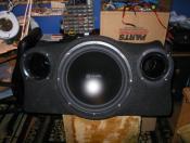
For some background on this. Im a mechanical engineering student at college. and year i had a statics and dynamics class followed by a mechanics of materials class. It basically taught be about how things are stress by forces and what works to stop stresses. One thing that was focus on are like and I beam the long skinny part of the I add a rigidness and also spaces the two top and bottom parts to a distance. that also add strength. The there are T beams which is just an I beam without a bottom. So i built a box a few months ago and used the t beam concept to brace my box. pic of the box i also added some dowel rods because the T beam concept would of had a disturbance on the air flow So this semester in class we have a program called Solidworks that we can build 3D models in and now we are learning how to make the program do stress analysis. So i decided to see how good the Tbeam concept worked. How i did it was a flat peice 30 by 17 inches, with all edged fixes in space like it would be attached to a box, Then put a force on the entire piece. I did 4 separate test each with the same force. the pics are just screenshots put in paint and saved. first i did just a .75" thickness to base things off of Then one of just doubling the thickness how some ppl do The pictures look the same, but the max stress on the double thickness is 1/4 that of the single thickness. Then i did a single 1 " dowel rod The max in this was actually double that of doubling the thinkness Then i did the Tbeam way. This way looks to be alot better, but the numbers actually show that around the edges (green spots) its a little more than the double thick board, the across the face is much better
-
ill be back soon with my stuff. taco bell just got home. hah
-
How does everyone brace their boxes? ive got some stuff im gonna post up soon of what i found out about bracing, but im wondering what everyone says first.
-
ive got two mojo 12's dual 4s forsale. still stiff 525 shipped
-
Even worse, in the related vids it says he has 10 bazooka 6x9s on the Outside of the truck.
-
Lil Wayne-A Millie (SPEEDY STYLE)
fritosaregood replied to Baydestrian's topic in Tunez - All things music related
wats the diff between chopped music and screwed music? screwed is slowed and chopped is remixed? my gf ask me the other day and i was like.. i think its that... -
yea, windows down work pretty good though, nothing close to doors open. i have been looking at some 4th order and 6 order boxes i got a q about certain 6th orders. whats the difference with a sixth order that just ports the front chamber and the back chamber, and one that ports the rear chamber into the front chamber and ports the front chamber?
-
I found out something nice today, if i have both front doors open, the sealed 15s move so much air.
-
i have use sealed, i started out with sealed, changed to ported, now ive got a sealed box again.
-
I was i bit more satisfied with my sealed 15s in my car today on the lows, but they dont get super low like i like. i had my windows down and my windows and doors were flexin a ton. I like being able to get down to atleast 20 hz. for more feeling than hearing though.